Anyone willing to lower gain try to add a FB Zobel, by forming a 100pf cap plus something around 10k resistor in series then adding parallel to R1.
I generally don't prefer to mess much around FB network as it may generate higher order odd order harmonics in spectrum.
Simpler the FB loop smoother the sound.
Edit: You can go as low as 21db, with the above FB Zobel
I generally don't prefer to mess much around FB network as it may generate higher order odd order harmonics in spectrum.
Simpler the FB loop smoother the sound.
Edit: You can go as low as 21db, with the above FB Zobel
Last edited:
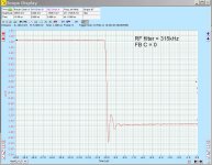
Here are the waveforms. These are triggering on the falling edge of a square wave, into an 18 Ohm load. The first set is with an input rf filter set to 315kHz. The overshoot of the stock configuration with a 1MHz filter would be even worse.
First is the "low-level" response. You can see this is still a 3VP-P waveform. Overshoot is about 25%, and it doesn't get any better at lower voltages. With 1uS per division, you can see the resonance is roughly 1.3MHz.
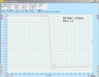
As the level is increased, the "overshoot" is increasingly swallowed by the finite slew rate of the device. Shown is 10VP-P. The overshoot is roughly the same magnitude as before, but it looks better because it is a smaller percentage of the overall waveform.
First is the "low-level" response. You can see this is still a 3VP-P waveform. Overshoot is about 25%, and it doesn't get any better at lower voltages. With 1uS per division, you can see the resonance is roughly 1.3MHz.
As the level is increased, the "overshoot" is increasingly swallowed by the finite slew rate of the device. Shown is 10VP-P. The overshoot is roughly the same magnitude as before, but it looks better because it is a smaller percentage of the overall waveform.
Attachments
Last edited:
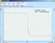
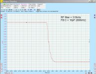
To optimize the feedback capacitor, I remove the input rf filter cap and tweak the falling edge response. With a 20kHz feedback R and 1.3MHz resonance, you could start with 6pF (1 / (2 * PI * Freq * R). I started with 8.2pF (1MHz) and that took care of most of the overshoot, but I decided to go to 10pF (800kHz) to be conservative. These are the same low-level and high-level waveforms, with 10pF feedback C and no input RF filter.
As you can see, it cleans up the high-level waveform really well; it doesn't even need an input filter. The low-level waveform still does, though.
As you can see, it cleans up the high-level waveform really well; it doesn't even need an input filter. The low-level waveform still does, though.
Attachments

Last edited:
Thanks for sharing the data Jbau. I'll have to see if I can get my 10pF silver mica installed or I can make an 11pF cap from a series 22pF NP0 500v 1206 SMT caps that I have a roll of 200. Soldered together and add some legs to become a nice through hole. I might have to take out the function generator to give it some square waves before and after.
Here are the waveforms. These are triggering on the falling edge of a square wave, into an 18 Ohm load. The first set is with an input rf filter set to 315kHz. The overshoot of the stock configuration with a 1MHz filter would be even worse.
What components were changed (and to what values) to get the “input rf filter set to 315kHz”?
or I can make an 11pF cap from a series 22pF NP0 500v 1206 SMT caps that I have a roll of 200. Soldered together and add some legs to become a nice through hole.
That doesn't sound like something you'd want to put in the feedback path! Use the mica...
What components were changed (and to what values) to get the “input rf filter set to 315kHz”?
In the stock BOM, you would change C10 to 680pF.
I just finished and listened to some LM3886 boards, and yesterday's impression of the 7293 sounding "a bit light" on the bottom was confirmed. It made me wonder about that bootstrap cap. Exactly what does it do? The data sheet isn't much help.
That doesn't sound like something you'd want to put in the feedback path! Use the mica...
In the stock BOM, you would change C10 to 680pF.
I just finished and listened to some LM3886 boards, and yesterday's impression of the 7293 sounding "a bit light" on the bottom was confirmed. It made me wonder about that bootstrap cap. Exactly what does it do? The data sheet isn't much help.
I have done this trick of converting tiny SMT NP0 caps into TH compensation caps all the time in some of my best amps when I don’t have the correct TH part on hand. I don’t see any reason why it would not be as good as silver mica as long as the voltage ratings were observed. It actually presents a smaller package that is probably less prone to RF pickup.
Can you be more specific about what “a bit light” on the bottom end means? Have you measured the DF difference between this amp and the LM3886?
The bootstrap cap allows the amp output swing to get closer to the rails without clipping.
@astromo: that’s pretty fast shipping to Oz!
I have done this trick of converting tiny SMT NP0 caps into TH compensation caps all the time in some of my best amps when I don’t have the correct TH part on hand. I don’t see any reason why it would not be as good as silver mica as long as the voltage ratings were observed. It actually presents a smaller package that is probably less prone to RF pickup.
Ah, ok, my concern was that it might have more inductance end-to-end.
Can you be more specific about what “a bit light” on the bottom end means? Have you measured the DF difference between this amp and the LM3886?
It's a more forward, less warm sound. Less body, more harmonics, if you will. Really shows on solo piano, orchestral, and female vocals. Bass on the LM3886 boards is more solid.
What is DF = Dissipation Factor?
My hunch this morning is, this is not a board-level problem, and the LM3886 may have lower output impedance vs freq. I'll be checking that out.
The bootstrap cap allows the amp output swing to get closer to the rails without clipping.
OK, thanks. I know you guys have tried different caps values there. Have you noticed an impact on tonal balance?
DF = Damping factor.
Damping factor is typically expressed as 8ohm/Zout where Zout is your output impedance.
But the actually useful figure is 8ohm/(Zout+8ohm). You get diminishing returns when Zout<<8ohm in terms of actual damping observed.
So I don't think the difference in damping between 3886 and 7293 is very significant at all, more likely the harmonics generated or freq/phase effects.
Last edited:
To date I've only known the formula DF = Znom/Zout. To avoid diminishing returns we also can it express in dB's 😉.
Best regards!
Best regards!
OK thanks. I'll be checking out the output impedance in the next day or two.
I know these headphones are very sensitive to it via their coupling transformers. When I first put them back into service, one channel sounded thin to me. Turns out the series 4R7 5W resistor on one channel had gone 0.4 Ohms high (probably due to carelesssness by moi in my younger days...). I replaced it and tonal balance was restored.
I know these headphones are very sensitive to it via their coupling transformers. When I first put them back into service, one channel sounded thin to me. Turns out the series 4R7 5W resistor on one channel had gone 0.4 Ohms high (probably due to carelesssness by moi in my younger days...). I replaced it and tonal balance was restored.
Yes, DF is damping factor. Since you are using it to drive what looks like a series of transformers to step the voltage up for an electrostatic headphone, it would be instructive to know the impedance that the transformer box presents to the amp. Is it nominal 8ohms? But since you say it is in the bass region, what is impedance circa 50Hz to 100Hz where the bass punch resides?
This is how I measure and calculate DF assuming an 8ohm load:
1. Set amp input using a sine wave gen at frequency of interest (100Hz) so that output into 8ohm load is exactly 1Vpp or 1Vrms (rms is nice as you can use a DVM - just be consistent)
2. Then disconnect the load or use say, 1k ohm load to represent a very light load and take voltage reading. It may be 1.1vpp (or rms) for example.
The difference 1.1v - 1.0v divided by 1.0v x load or 8ohms is the output impedance. Or 0.1 x 8 or 0.8ohms.
(1.1v - 1.0v)/(1.0v) x 8ohm
The DF is inverse of output impedance.
Often times though, a speaker with low Qts will appear to have more body and bass depth when played with a lower DF amp (like tube amps with a powerful motor full range driver in a back loaded horn).
What is the “Qts” of your headphone amp system?
I have network and impedance analyzers to measure output impedance directly. It's not necessary to "abstract" into DF. I'll post the results later.
I don't want to make your thread about my headphones, but since you asked, attached is the input impedance of the headphone system. Last month I ran a series of curves with different primary terminations. The top curve is the stock one. I'm using the next one down, the light blue one, which gives a load that is ~18.5 Ohms from 20Hz to 5kHz. That is why I have been using an 18 Ohm load in all my measurements.
Did you guys notice a tonal balance difference when you changed the bootstrap cap?
Attachments
Last edited:
Jbau,
This is really cool stuff and if you have not already done so, I would highly encourage that you create a new thread in the Headphone forum. This is good stuff to know that a basic chip amp can be used with transformers to drive electrostatic headphones.
Btw, 18ohms is a relatively “light” load and you might consider using a couple of TPA6120A2’s in parallel as they can drive 16ohm loads. Couple that with a composite amp structure with say, an OPA1656 as the voltage gain stage with the 6120 as a unity gain buffer and feedback goes into the 1656.
You would actually have a very good low distortion amp with plenty of power I think.
There are already some threads on this type of amp. As well as commercial implementations. I think Topping’s A30 is something worth looking at. It’s one of the highest rated headphone amps measured by ASR.
Last edited:
- Home
- Amplifiers
- Chip Amps
- Xmas Amp - Dibya's TDA7293 by Jhofland