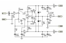
I have found many circuits using power transistors to boost the output of a chipamp, and have noted some impressive results here using the TDA7294 and lm3886, but there are many schematics with quite different layouts for the TDA20xx and LM1875T. I have quite a few of these chips and several types of power transistors on hand but have yet to successfully build a circuit that truly raises the output power to any remarkable level. I have
18-0-18 125VA on my psu netting 22-0-22, the load is 8 ohms speaker.
I have assembled the attached schematic and several other similar circuits using 0R33 5 watt resistors instead of the 0R22. and LM1875 instead of LM3886. The transistors do not boost at all even with full volume at the input. I will try other resistors, and have had thoughts on using 2 separate tfo's to alter the setup a bit and utilize the higher voltage of the output stage while keeping the op-amp at whatever voltage it is happiest.
If anybody has experience or helpful insight to share it would be greatly appreciated.
Attachments
I have found many circuits using power transistors to boost the output of a chipamp, and have noted some impressive results here using the TDA7294 and lm3886, but there are many schematics with quite different layouts for the TDA20xx and LM1875T. I have quite a few of these chips and several types of power transistors on hand but have yet to successfully build a circuit that truly raises the output power to any remarkable level. I have
18-0-18 125VA on my psu netting 22-0-22, the load is 8 ohms speaker.
I have assembled the attached schematic and several other similar circuits using 0R33 5 watt resistors instead of the 0R22. and LM1875 instead of LM3886. The transistors do not boost at all even with full volume at the input. I will try other resistors, and have had thoughts on using 2 separate tfo's to alter the setup a bit and utilize the higher voltage of the output stage while keeping the op-amp at whatever voltage it is happiest.
If anybody has experience or helpful insight to share it would be greatly appreciated.
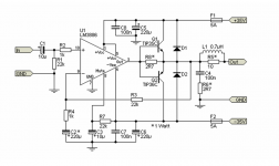
R8 and R9 need to have a higher value as they decide when Q1 and Q2 become active. Try with 1R. With 1R, Q1 and Q2 are activated around 650mA.
I tried the bridge configuration with 4 transistors, nothing but loud buzz through the speaker. op-amp alone sounds clean, and have seen up to 8 volts ac at the speaker with my multimeter. I swapped in some 3ohm resistors for R8 and R9 with no improvement, chip started getting warm. I am thinking this circuit may be a better approach...
Attachments
I tried the bridge configuration with 4 transistors, nothing but loud buzz through the speaker. op-amp alone sounds clean, and have seen up to 8 volts ac at the speaker with my multimeter. I swapped in some 3ohm resistors for R8 and R9 with no improvement, chip started getting warm. I am thinking this circuit may be a better approach...
This version with emitter outputs is easier to control than the first version with collector outputs. You may add some 0R22-0R33 emitter resistors if you want less cross-over distortion. For R8, I would use 1R in order to move the activation points further away and let the LM3886 handle delicate passages with low sound level on its own.
Was it Q1 and Q2 that became hot in the first configuration or was it the LM3886? 3R probably resulted in too high idle current through Q1 and Q2.
Bridging 2 amps can easily be done building 2 identical amps and use them with drv134 circuit. No reason to not work this way.
I tried the bridge configuration with 4 transistors, nothing but loud buzz through the speaker. op-amp alone sounds clean, and have seen up to 8 volts ac at the speaker with my multimeter. I swapped in some 3ohm resistors for R8 and R9 with no improvement, chip started getting warm. I am thinking this circuit may be a better approach...
No it would not the distortion would be awful no bias in the outputs. The overall gain doesn’t change and you gain nothing. Bridge two chips is much better. If you are using external transistors just build a transistor amp.
Thanks for all the input guys, much appreciated. FauxFrench it was the chip, not the transistors that got warm. Transistors had no conduction. Only about 100mv across power transistors and decreased as the input volume was increased. Just makes no sense to me and I do not have an o-scope yet. The very basic idea is that there should be enough voltage at the output of the op-amp to apply at the base of some power transistors and increast the output considerably. Many have done so with raving success but using TDA7294. I have a lot of these LM1875 chips and a bunch of power transistors on hand and should be able to work out an acceptable circuit with these components. Should be easily achieved, but so many different ways to carry out the objective, and ten times as many schematics. Seen plenty and have reproduced some of the circuits to the best of my ability with what I have on hand, but none of my attempts have been fruitful as of yet. It can be done.
LM1875 Based Simple Amplifier | Full Project Available
LM1875 Based Simple Amplifier | Full Project Available
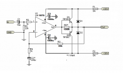
Just tried recent schematic with a few variations of R8, but performed best with that resistor omitted, though I could hear white noise that stopped as I unplugged transformer and circuit ran for a second from the voltage remaining in capacitors.
Voltage at output of IC was 3-4 volts AC, voltage at speaker was 4-5 volts AC. Minimal gain. Going to try stepping up the gain and more capacitors on the voltage rails close to LM1875 (Not using LM3886 as specified in schematic!)
Voltage at output of IC was 3-4 volts AC, voltage at speaker was 4-5 volts AC. Minimal gain. Going to try stepping up the gain and more capacitors on the voltage rails close to LM1875 (Not using LM3886 as specified in schematic!)
Hi, these external transistors are used when speaker has lower resistance than chip alone can handle at given power supply voltage. In example when chip is designed for 8ohms ,but you have 4ohms speaker or want to bridge .output. Amplifies not voltage,but allowable amperage at output,moves output current from chip.
Thanks for all the input guys, much appreciated. FauxFrench it was the chip, not the transistors that got warm. Transistors had no conduction. Only about 100mv across power transistors and decreased as the input volume was increased. Just makes no sense to me and I do not have an o-scope yet...................................
LM1875 Based Simple Amplifier | Full Project Available
If it is the chip that gets warm it is likely that your chip is oscillating. Neither LM1875 nor LM3886 are very generous with stability. In both your circuits, you can easily disable the power transistors by shorting base to emitter. Then, only the LM1875/LM3886 is active. If the circuit doesn't work well like that there is a general circuit problem and no need to involve the power transistors yet.
Are you using a wire-board for the circuit? Could you eventually post a photo of your board?
So here is what I have so far, white noise eliminated, sounds pretty decent and fairly loud, have not increased gain as of yet.
Q1 and Q2 have no bias on them with the bases shorted together. It will pass signal but is not a good circuit. Look at putting a Vbe multiplier and some emitter resistors if you want external transistors. This circuit also has increased losses so you actually get less ultimate power.
LM1875 CAN NOT be used with +/-35V rails, period.
I bet that´s why your chip is heating up so much, and it will probably blow soon.
I bet that´s why your chip is heating up so much, and it will probably blow soon.
He is not doing that...LM1875 CAN NOT be used with +/-35V rails, period.
I bet that´s why your chip is heating up so much, and it will probably blow soon.
Ok, now I see that contrary to schematic which he should have corrected, he´s actually using +/-22V.
Back to the original problem, he says he´s using an 8 ohm speaker and "adding transistors does not increase power".
Of course, he still has the exact same peak to peak swing as dictated by power supply rails, he has a higher current *capability* which will turn into higher power only if using lower load impedance.
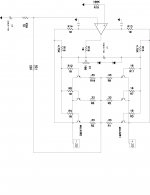
OK guys, plans now are to paralell my (2)- 8ohm speakers for a 4 ohm load and take some voltage measurements. The sound from the current scheme is notably stronger than the LM chip alone, though the gain was not a huge improvement. Thanks for pointing out the oversight on the voltage rails for my last schematic. The next share will be checked and double checked so I hope not to encounter any more mulligans.
I also started winding a transformer to push 30-0-30 to the circuit. Seems like an obvious boost to the scheme. Core is a bit small but if I encounter some sagging I will know for sure to up the core size and the tfo will be good to drive maybe a couple chips by themselves. Updates will be posted as progress ensues.
I also started winding a transformer to push 30-0-30 to the circuit. Seems like an obvious boost to the scheme. Core is a bit small but if I encounter some sagging I will know for sure to up the core size and the tfo will be good to drive maybe a couple chips by themselves. Updates will be posted as progress ensues.
Thanks wayne for your help. I thought there was a notable improvement in the output with the added output stage as shown, but with further checks today it appears that there is no conduction from the output stage. I am new to circuit design and have limited knowledge and experience with circuits and components but I suppose I was hoping to set up this output stage with a common emitter configuration for both voltage and current amplification. Now I am starting to wonder again if the best approach would be to feed higher voltage to the output transistors while limiting the voltage fed to the LM1875. Maybe a voltage regulator IC? or set up a transformer with separate dual rail outputs?
I really thought I had a successful amp running last night, no clue why the output seemed to be increased versus the chip alone. Crazy thing is I even measured the voltages and saw more at the output stage vs the output at #4 pin. No clue what that was all about. Now I am back in the boat just paddling...
I really thought I had a successful amp running last night, no clue why the output seemed to be increased versus the chip alone. Crazy thing is I even measured the voltages and saw more at the output stage vs the output at #4 pin. No clue what that was all about. Now I am back in the boat just paddling...
So now I am considering 2 options:
A) Single supply and single ended output to a single power transistor bringing the power output up to 60 volts max.
B) Using an output transformer of sorts, (perhaps a ferrite ring,) to separate the output from the chip into 2 individual outputs for the 2 power transistors so I can utilize the voltage and current gain characteristics of a common emitter configuration without tying the emitters together. (Dead short!)
There was mention of using a drv134 circuit which may be an option of sorts as well, but other than that I think the best advice so far was to build a discrete power amplifier.
If I don't catch a break on this venture soon that will likely be my direction.
- Status
- Not open for further replies.
- Home
- Amplifiers
- Chip Amps
- LM1875/TDA2050 adding output transistors.