Difficult times for sure, I hope the smiley face means you have decent options.
I'm sure I do. The smiley face was mostly because I've been procrastinating on it (and honestly too busy to focus on it). I've been operating with a 'mental' business plan but am at a point with my business where it would make sense to take half a step back and actually do some planning. Figure out where the market is at and where I want to go for the next five years. I need to do the same for Tom Christiansen Audio.
As far as hard times go: I managed to save some money while I worked for TI and I'm generally very frugal, so thankfully I've put myself in a position where I can hunker down and ride it out. April was rough. The summer was good. This month is definitely soft. Much of Europe is in lockdown. As is Eastern Canada. I'm sure business will pick back up once the world reopens.
So now's a good time to tap the brakes on my project spend and do some planning.
1- if the type of noise I hear sounded of SMPS origin,
No idea, honestly. If you have an FFT plot (80-100 kHz BW preferably) with a reasonable frequency resolution I can make a better guess. I would be surprised if anything SMPS-related showed up at audio frequencies.
2- if the Mean Well units* radiate high frequency EMI from a specific area of the module, where my layout increases the potential for proximity coupling,
Not that I've noticed. Most SMPSes start by rectifying the incoming mains. I would stay away from that area as that tends to emit some 120 Hz hum. That said, the Mean Well SMPSes have quite a few EMC certifications, so I would be surprised if they emit stuff that interferes with your circuit.
What could be going on is that the two SMPSes are operating at slightly different frequencies and that you're hearing the beat products of their switching frequencies. But if that was the case, I would expect it to impact both sides and not just the right side.
It may be worthwhile to double check that you didn't skip a solder joint on one of the offending LM3886DR boards. A bad connection in the input section could have all sorts of odd effects.
3- if the physical separation of the stacked bridged-boards, or my input wiring scheme, makes it hyper-susceptible to EMI.
I don't think so.
*I'm using the EPP-400-27 as opposed to the low-EMI rated RPS-400-27 because I got them dirt cheap.
I have not tested the EPP-400. I have only had good experiences with the RPS-400-27(-C). The RPS-400-36(-C) can be whiny at light load, so I'd steer clear of that one.
Tom
Success! Armed with the belief the SMPS were not the problem, I pulled the noisy LM3886DR pair, connected them to a linear PS - and with earbuds, traced the offending noise to one board. Checked it over carefully, then replaced the LM3886 chip, and violà, all quiet! DC offset for the new chip is the same ~4.5mV as all the others, resulting in .3mV for the bridged pair. I had purchased extra 3886's in case offset was excessive, but glad I had it to replace the noisy one! I'm a bit disappointed with the chip, being either out of spec (defective) or at the upper limit of noise which was audibly inferior in my application.
With it buttoned up, everything works perfectly. Hiss from all channels can only be heard with my ear an inch from the driver. My concerns about the Mean Well SMPS have been quelled and I'm thrilled they were not the issue. Thank you Tom for the great products, advice and assistance. It's truly awesome to be able to converse with an EE!
Let the critical listening begin!
It is possible that an ESD strike to the input pins of the chip caused damage to the input transistors, resulting in an increase in noise. It could have happened anywhere between the factory and finished PCB, or even after mounting to the PCB. Chips have built-in ESD protection but it's easy to exceed that protection by a zap that's still too small for you to feel.
Brian - definite food for thought. While I always touch a grounded surface before removing semi-conductors from their anti-static bag, I don't use a strap (maybe I should be?). I've often wondered how worrisome an issue ESD actually is, but generally assumed the higher voltage devices (like the LM3886) should be pretty tough. I also hoped an ESD hit would cause total failure rather than diminished performance, but I'm sure that depends on the device and the discharge. I was also taught to believe that semi-conductors were "pretty safe" from ESD once in their circuit, but no doubt there are exceptions to that as well.
Thanks for your input, I'd appreciate any comments about my assumptions.
Thanks for your input, I'd appreciate any comments about my assumptions.
Having the chip soldered into the circuit does reduce the ESD susceptibility somewhat, but not enough to rely on it to fully protect the IC. ESD requirements have been tightened by the various semiconductor manufacturers through the years. In "the old days" 2000 V human body model (HBM) was required for ESD compliance. That may sound like a lot with 2 kV applied to a low-voltage IC, but HBM is pretty easy to pass due to its series resistance and inductance. These days more stringent models, such as the charged device model (CDM) and machine model (MM) are applied. As result, more modern ICs will generally survive higher voltage zaps than older ICs. Recall the LM3886 is 25 years old.
It's easy to generate high voltages just by shifting in your chair and such. The climate in Calgary is dry, especially in the winter. Indoor relative humidity down around 15-20 % is common. So I pick up quite a bit of charge just getting up from my desk chair. For a while I would ground myself on a grounded screw by the light switch for the room, but found that rather painful at times. I decided to explore some options for how to reduce the pain, so I started adding series resistance. Once I got up around 1 MΩ, the pain level started to go down ... until the spark just jumped across the resistor instead. That's 9-10 mm of spark. Figure 1 kV/mm or about 10 kV.
My work surface has a grounded electrostatic dissipative mat on it. I maintain good contact with the mat as I'm working. I wear a wrist strap when necessary. The mat I use is 80x160 cm, so a bit pricey ($80, I think it was). You can find smaller ones for less.
All my fully assembled products are assembled professionally. The assembly guys take ESD seriously and take all the necessary precautions to prevent ESD damage. This includes ESD smocks, grounded footwear, wrist straps, and ESD safe workbenches and chairs. I would also expect them to apply ESD dissipative wax on their shop floor. We used to do that regularly in our lab at TI.
Sadly, ESD strikes can result in latent damage. The damage may reveal itself months or years later. Or it may result in reduced performance, as in your case.
Tom
Hi DIY folks,
I finished my LM3886DR a few weeks ago. This post would have been written earlier, but I was too busy listening to my new amp!
Some background: this was one of my first DIY audio projects. The LM3886DR is hooked up to an eBay version of a B1 buffer PCB that I built last year. The LM3886DR is replacing a XY LM3886 amp, which was also from eBay. The B1 also got some upgrades. Allow me to share some of the lessons I learned while doing these projects, and some photos of course.
The B1 used to be just a PCB and volume pot in a box, hooked up to a wall wart and of course the input and output RCA's. My Ali Express wall wart died on me within 6 months, so I had a 24v DIN rail PSU in there for a while.
The new version of the B1 has the LSK JFET's instead of the Toshiba clones I had before. The new JFET's are soldered to the board instead of placed in sockets. I also replaced some resistors that had their leads very close to some other leads. The resistors I used are mostly too large for my PCB, so that was another mistake that I'll have to live with for now.
The signal wires to the volume pot were picking up a lot of noise, so I drastically decreased the length of those by bringing the pot inside the case. I also removed all screw terminals for the signal and soldered everything straight to the board. Previously, I used wires I ripped out of a UTP cable, but I think the quality was pretty crappy. They were also shitty to work with, sometimes breaking right after you soldered a connection. Now I used bare pure copper wire and put teflon isolation over it myself.
The final B1 upgrade is a proper PSU, one of those Studer 900 boards from Audiophonics. I was aiming to get it at 18v but had some issues with that so it's running on 23.4v now, which should be fine for the B1. I replaced the cap on the PSU with a Mundorf one.
All problems I had with this preamp are solved and it sounds good.
On to the main topic at hand, the LM3886DR. The XY amps started to die on me. The chips on those are probably clones, as I bought two complete PCB's with the parts installed on eBay, for the price of a single LM3886 chip at Mouser. I had the chips screwed straight to the coating on my chassis without any thermal paste or whatever, I thought they ran pretty cool because the chassis stayed cool, until I felt the bolt, which was almost scorching. I started hearing clipping noises more and more (I think, just crackles and pops) until I finally couldn't take it anymore. Before the XY amps deteriorated they didn't sound too bad to be fair (I wouldn't know about any measurements though, probably pretty crappy). They didn't last a year though.
Another mistake with version one of my LM3886 amp was the transformer, probably a pretty classic mistake. I was aiming for 32v DC input to the XY amp boards, so I ordered a 2x32V transformer.. Then I learned about AC/DC conversion, especially with a traditional PSU with large caps. This probably didn't help the longevity of the XY boards either haha. They were operating at about 44v DC because of this mistake (you have to multiply the AC voltage by roughly 1.4 to get the DC voltage at the PSU output after the caps).
The PSU was also an eBay board, with 4x 10.000uF caps, also from eBay, the Nover ones. I wanted to keep the PSU, then I read something about those Nover caps somewhere and concluded they're probably fakes too. I skimped on those in my first build, they were about 15 euro for the 4 of them. So, I got a new PSU. I had already ordered the LM3886 boards from Tom before I found out about this, otherwise I would have ordered a PSU from Tom too. I'm in the Netherlands though so it was more convenient to get a board from Audiophonics. The new board has caps from Cornell, the Dubilier type, 4x 22000uF 50V. The Audiophonics board has "faston" connectors that don't live up to their name, they're so tight that you need pliers to wiggle them off, taking care not to destroy your new PSU.
I learned about the concept of "crest factor" from Tom's awesome LM3886DR design documentation, so I got a 2x20v (300VA) transformer. I bought it at ringkerntrafo.nl, a Dutch supplier of good toroids for audio projects. I also got some proper heat sinks. My first order is still pending, from Fischer Elektronik, but I got impatient so I got two heat sinks that were in stock at Audiophonics. I think they're large enough. I used the keratherm pads and the sinks stay cool to the touch.
There was a statement about chassis work taking up 90% of the build time and that wasn't a lie! The boards are pretty easy to solder (although the bit a for posts before got me paranoid, so I soldered the LM3886 chips wearing latex gloves, I don't have any antistatic gear), but I don't have a drill press so ventilation holes and such took me a few days of messing around. The layout I decided on has short signal wires as the main design choice, but that puts the heat sinks on the inside of the case. I aimed for a chimney effect for ventilation with more open surface area on the bottom than on the top, so I cut out a rectangular shape on the bottom and drilled 5mm holes into the top within the rectangular shape that the bottom has cut out. 82 holes to measure, punch and drill into 2mm steel, sweat was involved..
The grounding on the first version was a mess. I gleaned some ideas from random chipamps and just put things together. For the LM3886DR I just grounded the chassis, PSU output and earth of the IEC socket to each other. I drilled some of the chassis coating away and put a tooth lock washer on that, with solder lugs and nuts on top of that. Using a multimeter shows all ground points in the amp to have 0 resistance to each other so I think things are OK like this.
These amps are still prototypes as far as I'm concerned. I kept my old cases and just ripped out all the old parts and started over. I like the cases, I bought them at a local army dump. I think there used to be some security equipment in those, they were probably on the wall of a random office building before they ended up in my living room with amps in it. One of the cases had and still has a sticker that says something like "Absolutely never turn off!!!" in Dutch, which speaks volumes to the importance of music.
I didn't went overboard with the price of the connectors, but I did replace all RCA's and binding posts with some proper quality gold plated types. I chose connector designs with lots of plastic so that I could easily keep everything isolated from the chassis using the crude tools I had available.
So, with both of these finished, it was time to test everything and try them out. The LM3886DR sounds amazing! The XY boards where already putting my old NAD C320BEE to shame, but they had their problems. Now I have a problem-free implementation of a LM3886DR circuit and I'm very happy with it. My own Mission floorstanders have an input sensitivity of 91dB, which is pretty good. More than enough gain for me, casual listening has the volume pot between 9 and 11 on the clock, loud listening at 12 so with the pot turned half the way of its range. The pot is the standard Alps blue.
Since completing this build I have been listening very extensively and I'm thoroughly impressed. This setup could serve me for years if nothing breaks down. I also took the new amps to my friends place and spent a long evening listening over there. My friend recently bought some KEF Q500 floorstanders. They're much nicer than my Missions, but the sensitivity is 87dB I think and that makes quite a difference. The LM3886DR does the job but it doesn't have much headroom. To our ears, things mostly sound nice, but my friend is very critical and we pinpointed some things that are still going wrong (mostly sharp highs, not everything is being nice to our ears, and also more distortion and losing some separation between different instruments at "tough" music parts at higher volume). The source for this session was a Logitech bluetooth thingy though, which might be a bottleneck although it's not bad at all. My friend is still looking for a good match for his Q500's, we might eventually build something for him too. I suspect he needs a bit more power though, maybe something from Hypex or the Modulus-686, although both roads are significantly more expensive than the setup that I now have. Maybe a Mod-86 with additional gain in the preamp stage would make sense.
Just last week I read Tom's post about solder and checked the solder I used for these projects right away. I used Cardas Quad Eutectic which was good to work with but has an "active" type flux core, and I didn't know flux cleaning was a thing. Having water near a PCB was and still kinda is a crazy idea to me, so I need to research this more. Hopefully I don't get too much corrosion issues any time soon. I'll probably look for a solder that allows me to build quality amps while skipping the cleaning. I did have soldering experience before starting this project, and I'm confident that I made nice joints everywhere.
I got the advice to skip the LM3886DR and build the Mod-86 right away. All things considered, that was sound advice, but my ignorant *** needed to follow my own learning path and I'm still happy that I did it. One of my next projects will be two Mod-86 mono blocks and I won't have any mistakes like corrosive uncleaned solder flux in those. Today I pulled the trigger and ordered the Mod-86 boards, Power-86 boards to go with them and a universal buffer. In the mean time I read up on balanced amps, and Tom's recent preamp article got me inspired to get started on some more projects. I also ordered a HP22 headphone amp board while I'm at it, as the PCB is very affordable and I'm curious what my Beyerdynamic DT 990 pro will achieve on that, altough it's 600 ohm and I don't know how the amp will handle that. I'm thinking it should beat a PC or laptop sound card though.
If you want a very fine sounding amp and a good learning project, I can highly recommend the LM3886DR project. Thank you Tom for putting in the time, making these products available and educating folks like me.
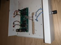
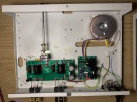
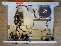
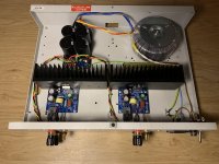
So to finish my epistle, some photographs. In order: my old B1, new B1, old LM3886 (XY amp), new LM3886DR.
I finished my LM3886DR a few weeks ago. This post would have been written earlier, but I was too busy listening to my new amp!
Some background: this was one of my first DIY audio projects. The LM3886DR is hooked up to an eBay version of a B1 buffer PCB that I built last year. The LM3886DR is replacing a XY LM3886 amp, which was also from eBay. The B1 also got some upgrades. Allow me to share some of the lessons I learned while doing these projects, and some photos of course.
The B1 used to be just a PCB and volume pot in a box, hooked up to a wall wart and of course the input and output RCA's. My Ali Express wall wart died on me within 6 months, so I had a 24v DIN rail PSU in there for a while.
The new version of the B1 has the LSK JFET's instead of the Toshiba clones I had before. The new JFET's are soldered to the board instead of placed in sockets. I also replaced some resistors that had their leads very close to some other leads. The resistors I used are mostly too large for my PCB, so that was another mistake that I'll have to live with for now.
The signal wires to the volume pot were picking up a lot of noise, so I drastically decreased the length of those by bringing the pot inside the case. I also removed all screw terminals for the signal and soldered everything straight to the board. Previously, I used wires I ripped out of a UTP cable, but I think the quality was pretty crappy. They were also shitty to work with, sometimes breaking right after you soldered a connection. Now I used bare pure copper wire and put teflon isolation over it myself.
The final B1 upgrade is a proper PSU, one of those Studer 900 boards from Audiophonics. I was aiming to get it at 18v but had some issues with that so it's running on 23.4v now, which should be fine for the B1. I replaced the cap on the PSU with a Mundorf one.
All problems I had with this preamp are solved and it sounds good.
On to the main topic at hand, the LM3886DR. The XY amps started to die on me. The chips on those are probably clones, as I bought two complete PCB's with the parts installed on eBay, for the price of a single LM3886 chip at Mouser. I had the chips screwed straight to the coating on my chassis without any thermal paste or whatever, I thought they ran pretty cool because the chassis stayed cool, until I felt the bolt, which was almost scorching. I started hearing clipping noises more and more (I think, just crackles and pops) until I finally couldn't take it anymore. Before the XY amps deteriorated they didn't sound too bad to be fair (I wouldn't know about any measurements though, probably pretty crappy). They didn't last a year though.
Another mistake with version one of my LM3886 amp was the transformer, probably a pretty classic mistake. I was aiming for 32v DC input to the XY amp boards, so I ordered a 2x32V transformer.. Then I learned about AC/DC conversion, especially with a traditional PSU with large caps. This probably didn't help the longevity of the XY boards either haha. They were operating at about 44v DC because of this mistake (you have to multiply the AC voltage by roughly 1.4 to get the DC voltage at the PSU output after the caps).
The PSU was also an eBay board, with 4x 10.000uF caps, also from eBay, the Nover ones. I wanted to keep the PSU, then I read something about those Nover caps somewhere and concluded they're probably fakes too. I skimped on those in my first build, they were about 15 euro for the 4 of them. So, I got a new PSU. I had already ordered the LM3886 boards from Tom before I found out about this, otherwise I would have ordered a PSU from Tom too. I'm in the Netherlands though so it was more convenient to get a board from Audiophonics. The new board has caps from Cornell, the Dubilier type, 4x 22000uF 50V. The Audiophonics board has "faston" connectors that don't live up to their name, they're so tight that you need pliers to wiggle them off, taking care not to destroy your new PSU.
I learned about the concept of "crest factor" from Tom's awesome LM3886DR design documentation, so I got a 2x20v (300VA) transformer. I bought it at ringkerntrafo.nl, a Dutch supplier of good toroids for audio projects. I also got some proper heat sinks. My first order is still pending, from Fischer Elektronik, but I got impatient so I got two heat sinks that were in stock at Audiophonics. I think they're large enough. I used the keratherm pads and the sinks stay cool to the touch.
There was a statement about chassis work taking up 90% of the build time and that wasn't a lie! The boards are pretty easy to solder (although the bit a for posts before got me paranoid, so I soldered the LM3886 chips wearing latex gloves, I don't have any antistatic gear), but I don't have a drill press so ventilation holes and such took me a few days of messing around. The layout I decided on has short signal wires as the main design choice, but that puts the heat sinks on the inside of the case. I aimed for a chimney effect for ventilation with more open surface area on the bottom than on the top, so I cut out a rectangular shape on the bottom and drilled 5mm holes into the top within the rectangular shape that the bottom has cut out. 82 holes to measure, punch and drill into 2mm steel, sweat was involved..
The grounding on the first version was a mess. I gleaned some ideas from random chipamps and just put things together. For the LM3886DR I just grounded the chassis, PSU output and earth of the IEC socket to each other. I drilled some of the chassis coating away and put a tooth lock washer on that, with solder lugs and nuts on top of that. Using a multimeter shows all ground points in the amp to have 0 resistance to each other so I think things are OK like this.
These amps are still prototypes as far as I'm concerned. I kept my old cases and just ripped out all the old parts and started over. I like the cases, I bought them at a local army dump. I think there used to be some security equipment in those, they were probably on the wall of a random office building before they ended up in my living room with amps in it. One of the cases had and still has a sticker that says something like "Absolutely never turn off!!!" in Dutch, which speaks volumes to the importance of music.
I didn't went overboard with the price of the connectors, but I did replace all RCA's and binding posts with some proper quality gold plated types. I chose connector designs with lots of plastic so that I could easily keep everything isolated from the chassis using the crude tools I had available.
So, with both of these finished, it was time to test everything and try them out. The LM3886DR sounds amazing! The XY boards where already putting my old NAD C320BEE to shame, but they had their problems. Now I have a problem-free implementation of a LM3886DR circuit and I'm very happy with it. My own Mission floorstanders have an input sensitivity of 91dB, which is pretty good. More than enough gain for me, casual listening has the volume pot between 9 and 11 on the clock, loud listening at 12 so with the pot turned half the way of its range. The pot is the standard Alps blue.
Since completing this build I have been listening very extensively and I'm thoroughly impressed. This setup could serve me for years if nothing breaks down. I also took the new amps to my friends place and spent a long evening listening over there. My friend recently bought some KEF Q500 floorstanders. They're much nicer than my Missions, but the sensitivity is 87dB I think and that makes quite a difference. The LM3886DR does the job but it doesn't have much headroom. To our ears, things mostly sound nice, but my friend is very critical and we pinpointed some things that are still going wrong (mostly sharp highs, not everything is being nice to our ears, and also more distortion and losing some separation between different instruments at "tough" music parts at higher volume). The source for this session was a Logitech bluetooth thingy though, which might be a bottleneck although it's not bad at all. My friend is still looking for a good match for his Q500's, we might eventually build something for him too. I suspect he needs a bit more power though, maybe something from Hypex or the Modulus-686, although both roads are significantly more expensive than the setup that I now have. Maybe a Mod-86 with additional gain in the preamp stage would make sense.
Just last week I read Tom's post about solder and checked the solder I used for these projects right away. I used Cardas Quad Eutectic which was good to work with but has an "active" type flux core, and I didn't know flux cleaning was a thing. Having water near a PCB was and still kinda is a crazy idea to me, so I need to research this more. Hopefully I don't get too much corrosion issues any time soon. I'll probably look for a solder that allows me to build quality amps while skipping the cleaning. I did have soldering experience before starting this project, and I'm confident that I made nice joints everywhere.
I got the advice to skip the LM3886DR and build the Mod-86 right away. All things considered, that was sound advice, but my ignorant *** needed to follow my own learning path and I'm still happy that I did it. One of my next projects will be two Mod-86 mono blocks and I won't have any mistakes like corrosive uncleaned solder flux in those. Today I pulled the trigger and ordered the Mod-86 boards, Power-86 boards to go with them and a universal buffer. In the mean time I read up on balanced amps, and Tom's recent preamp article got me inspired to get started on some more projects. I also ordered a HP22 headphone amp board while I'm at it, as the PCB is very affordable and I'm curious what my Beyerdynamic DT 990 pro will achieve on that, altough it's 600 ohm and I don't know how the amp will handle that. I'm thinking it should beat a PC or laptop sound card though.
If you want a very fine sounding amp and a good learning project, I can highly recommend the LM3886DR project. Thank you Tom for putting in the time, making these products available and educating folks like me.
So to finish my epistle, some photographs. In order: my old B1, new B1, old LM3886 (XY amp), new LM3886DR.
Attachments
Last edited:
Wow. That's quite the journey. It goes to show that going cheap often ends up being more expensive in the end. I'm glad you're enjoying the LM3886DR. Also glad the Alibaba power brick didn't catch your house on fire when it died...
The 'naked' LM3886 does have higher distortion at higher frequencies. I bet that's what's causing the slight harshness in the highs. The Modulus-86 solves that by applying error correction to the LM3886. Maybe there's a Modulus-86 in your future?")
If you don't have ESD protective gear, the best you can do is to make sure you leave the ESD sensitive parts in their bags for as long as possible. Only open the bag once you're ready to use the parts, and make sure the PCB, the bag, and you are at the same potential by touching both before you open the bag.
A small ESD mat is pretty inexpensive and, actually, Digikey seems to have the best prices on those. Better than that online bookstore, the auction site, etc. Just make sure the mat is grounded when you use it.
That said, I've never damaged a part with an ESD strike (knock on wood). That's probably because I've spent most of my life in damp environments near the coast. Now I'm 1000 km from the nearest ocean in a very dry environment. My hygrometer currently reads 24% RH. It'll drop below 20% over the weekend as the outdoor temperature isn't supposed to exceed -20ºC for the next few days.
I also ship circuits to customers so I have to worry more than the average hobbyist about ESD protection.
The assembly house I use for my fully built modules go all the way with ESD protection: ESD wax on the floor, ESD safe chairs, wrist straps and/or heel straps, ESD dissipative mats on the work surfaces, smocks, etc., etc. Plus they train their employees in how to use all of that and test the wrist/heel straps daily. But then again, they build mission-critical equipment and can't have it fail in the customers' hands due to an ESD strike.
Tom
The 'naked' LM3886 does have higher distortion at higher frequencies. I bet that's what's causing the slight harshness in the highs. The Modulus-86 solves that by applying error correction to the LM3886. Maybe there's a Modulus-86 in your future?
If you don't have ESD protective gear, the best you can do is to make sure you leave the ESD sensitive parts in their bags for as long as possible. Only open the bag once you're ready to use the parts, and make sure the PCB, the bag, and you are at the same potential by touching both before you open the bag.
A small ESD mat is pretty inexpensive and, actually, Digikey seems to have the best prices on those. Better than that online bookstore, the auction site, etc. Just make sure the mat is grounded when you use it.
That said, I've never damaged a part with an ESD strike (knock on wood). That's probably because I've spent most of my life in damp environments near the coast. Now I'm 1000 km from the nearest ocean in a very dry environment. My hygrometer currently reads 24% RH. It'll drop below 20% over the weekend as the outdoor temperature isn't supposed to exceed -20ºC for the next few days.
I also ship circuits to customers so I have to worry more than the average hobbyist about ESD protection.
The assembly house I use for my fully built modules go all the way with ESD protection: ESD wax on the floor, ESD safe chairs, wrist straps and/or heel straps, ESD dissipative mats on the work surfaces, smocks, etc., etc. Plus they train their employees in how to use all of that and test the wrist/heel straps daily. But then again, they build mission-critical equipment and can't have it fail in the customers' hands due to an ESD strike.
Tom
Last edited:
Just finished a Neurochrome amp build!!
2 x LM3886DR, Power 86 in a Mini Dissipante case.
I don't have much electronic knowledge but I can solder, needed a new amp so I ordered the PCB's from Tom. Then the parts from Mouser. Great system in place from Tom where you just plug in the project number on the mouser site and all the parts list drop into your cart..
The PCB's arrived and the manuals were downloaded. Great instructions.
The first victory was when I built the Power 86, switched it on, expecting a bang and flash at least, but no, it was reading exactly the right voltage....from there the amp boards were quickly built.
As others have said the case takes some work but it looks superb when finished. As to the sound...all I can say is it was way better than I expected with an amazing soundstage and clarity. Thanks to Tom at Neurochrome for a great product, also thanks to others on this thread that inspired me especially DaveFred.....
Hello,
Would it be possible to use the LM3875 in this, making sure not to connect any pins that aren't compatible? If so then what to do with the mute section on the amp? I ask because I have a bunch of these ICs sitting around.
I know the chip will need to be configured a bit differently, nothing too hard though for a gaincloner.
You would have to bend the two input pins so they end up in the right holes on the PCB and generally observe the pinout differences, but those things aside I don't see any issues.
The LM3876, on the other hand, can drop directly into the LM3886DR PCB without any modifications.
Tom
The LM3876, on the other hand, can drop directly into the LM3886DR PCB without any modifications.
Tom
- Home
- Amplifiers
- Chip Amps
- Neurochrome LM3886DR Build