As I said before I have a broken function generator (cheap Siglent crap), so I can't test anything right now.
Sounds like you should get off the computer and start fixing your signal generator, then...


If you decide to get another sig gen, I recommend the ancient HP 3312A. Those things are just about bomb proof. I picked mine up in calibrated condition on eBay for $150 a few years back.
~Tom
So far I've tested most things (clipping, messing with the supply, sticking a 1000uF cap on the output etc..) and it recovers OK. I'll try what you said though. I can perfectly well accept that this circuit is far from bomb proof
Now you mention it, there is an HP 3314A (old one with the proper clicky buttons) somewhere that I can use...
Now you mention it, there is an HP 3314A (old one with the proper clicky buttons) somewhere that I can use...
Here's a stability test for you: Run a square wave in at 10 kHz. Adjust the amplitude such that you get about 2/3 of the full swing on the output (so 20 Vp if the supply is 30 V) into an 8 ohm load. Measure the amplifier output using an oscilloscope with at least 10 MHz bandwidth. Apply 10 nF of load cap in parallel with the 8 ohm. Then try 22 nF, 47 nF, 100 nF, 220 nF, 470 nF, 1 uF, 2.2 uF, 4.7 uF, 10 uF. I guarantee you that your circuit will oscillate. I also bet that you have significant ringing on the output waveform even with a low capacitive load of, say, 1 nF.
Many electrostatic loudspeakers fall in the range of 1 uF to 22 uF, so this test is actually pretty relevant.
The 3314 looks like a pretty nice generator. That'll certainly do the job.
~Tom
Many electrostatic loudspeakers fall in the range of 1 uF to 22 uF, so this test is actually pretty relevant.
The 3314 looks like a pretty nice generator. That'll certainly do the job.
~Tom
So far I've tested most things (clipping, messing with the supply, sticking a 1000uF cap on the output etc..) and it recovers OK.
What do you mean by "it recovers OK"? How does the amp perform during the test?
If the amp oscillates with 1 nF load but does not oscillate when the 1 nF is removed, is that a solid design? I think not. In particular as many speaker cables and speaker drivers will present more than 1 nF of capacitance to the amplifier.
It is possible that the amp is stable with 1000 uF connected. This is likely enough to make the amp completely load compensated, i.e. the load capacitance forms the dominant pole. The tricky range tends to be the 10 nF .. 10 uF range. You can convince yourself of this pretty easily by running a simulation.
~Tom
Really interesting information, thanks.
Some datasheets mention it, some don't, but you've probably exceeded the safe output capacitance limit for using the 3x7 regulator pair without protection diodes. Consider also some amount of Cadj.Anyway, any suggestions/comments/criticisms?
The suggestions to have a look with a reasonable scope around clipping as well as the notion of spending some time with an up to date set of models in TINA aren't bad ones. Whilst the models aren't all they could be Tom and I've been back and forth across this space this quite a bit and they do capture quite a bit of real behaviour. If you know your levels and hence can guarantee the 3886 operates below its clipping voltages there's a lot less to worry about in regards to recovery from the control loop opening.
Other way round really. Minus ibnufinity dB distortion into a resistor happens mainly because of high loop gain. Which, in turn, means the amp is at least in principle able to provide good error correction to a real speaker. A routine problem is the control loop lacks the PSRR to be able to achieve the accuracy needed to make full use of the loop gain; a 3x7 pair and op amps with solid PSRR like the LME49700s solve this rather nicely.I do however believe that the side effects of the lower distortion is what makes the difference
In typical power amp gain structures low voltage offset's not much of a servo requirement. The worst case 6mV on a TL072 is around half to a quarter of typ on a 3886. And, with 20dB gain, the source offset would have to be under 300uV to beat a TL072 typ. That's unlikely. For example, building a differential DAC output buffer with an offset under 300uV requires 49700 class voltage offsets with FET bias currents and 80+dB CMRR.You may want to redo the math on that one... I doubt you get much benefit of the DC servo in terms of output offset unless you use an op-amp with low input voltage offset and low input bias current.
I did the math for 49720 servos some years back as National's published worse in at least one app note. If this amp's running around room temperature with a typ input bias current offset the servo will yield a mV or a few offset as IO390's mentioned. That's is widely considered fine for speakers and certainly better than boosting a source offset of a few mV by 20dB. However, the worst case offset's around 90mV for this circuit. In which case one might well be better off without the servo. Not what I'd call commercial production quality but neither does that seem to be a goal for this build.
However, the worst case offset's around 90mV for this circuit. In which case one might well be better off without the servo.
That's exactly where I landed on using the LME49710 as a DC servo. The compactness of the layout is nice with the dual op-amp, but the high worst case input bias current is a deal breaker, sadly.
~Tom
does anyone need the extra zero in the THD, ~200 Ohm equivalent noise vs say a OPA827 modern fet input op amp?
I was a little over dramatic earlier but the stability does need work - rolling the integrator time constant to lower frequency cuts into the added loop gain but I don't see any help for it if you want ~60 degree phase margin
I was a little over dramatic earlier but the stability does need work - rolling the integrator time constant to lower frequency cuts into the added loop gain but I don't see any help for it if you want ~60 degree phase margin
Last edited:
does anyone need the extra zero in the THD
The biggest benefit of the composite topology that I see is that the PSRR is increased dramatically. I'm getting the same performance on the Modulus-86 composite amp when powered by a pair of Agilent E3632A power supplies ($1200/each) as I do with a regular unregulated supply consisting of a toroid, rectifier bridge, and 2x22000 uF reservoir cap.
When the naked LM3886 is subjected to the same experiment, the THD performance degrades by about 30x.
If I want a transparent "wire with gain" kind of amp, I do want at least two zeros on the THD across the audible range.
~Tom
Last edited:
That's a lot of responses
I was actually planning to use an OPA827 for this project, but I only had one of them in the drawer vs. a number of LME49720s. So that's what drove my decision. When this abortion of a design is sorted I'll probably switch to an SOIC LME49710 and another suitable opamp for the servo.
Regarding the regs, there's a couple components that I didn't include on the schematic. Protection diodes are there (not added in the photo in the OP) as well as local 0.1uF decoupling caps for the regs and the LM3886. I didn't add any caps to the adjust pin but that wouldn't be hard to do.
By the way, again in reference to Twest's post, when you say "3x7 pair", what do you mean? I've not seen that term before, or maybe I'm just going senile.
As for stability with capacitance on the output, I did test this a little. 1nF did bugger all, 10 caused some incredibly minor ringing, 100nF introduced a little bit of ringing and 1uF caused a fair bit, probably too much. I didn't test any more than 1uF but I'll do this and get back with some actual results. When I say it recovers OK, I was talking about the shorting. For example, when shorted, the output dies (as one would expect), and when the short is removed, the output reappears without any fuss. I would call that recovering OK.
I will get back with some actual measurements soon enough, once everything is working on the bench. "It seems to work" isn't very definitive so I apologise for the ambiguity thus far.
I have a very similar composite (49720+LM4780) which runs way more local compensation for the master OP just to be safe at any conditions, this also needs local and global gains to be the same.
A while back you posted a schematic showing your re-referenced ground solution to LM3886's poor -ve rail PSRR. Have you compared your composite's PSRR with that implementation? I'm curious to know if the re-referenced ground gives similar results for PSRR in practice to a composite. Clearly it won't match the THD but that's not a concern for me.
No, I missed that chance for a comparision, sry. But the PSRR of the composite is excellent and that was a design requirements it is fed from a quite noisy single rail (but no output cap). Will try to do this A/B for TDA7293's which should be somewhat similar to 3886's in PSRR issues.
Member
Joined 2009
Paid Member
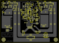
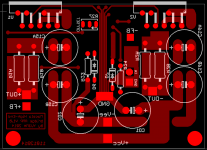
The full version original thread need to be translated from here, but it s a lot more technical : Bato MM-Amp (LM-most by macolakg) : Dokumentacija It seems that the original forum gone down and all was copied on yu3ma s forum. V1 smd pcb is very cool...
That forum isnt accepting new registrations at present, can you post more here?
Here a little link to start about it (pcb version 0.8), uploaded below gerber and bom of v1. Just finished one, it works like a charmThat forum isnt accepting new registrations at present, can you post more here?
. Got 5 pcb left if interested.Attachments
Last edited:
Here a little link to start about it (pcb version 0.8), uploaded below gerber and bom of v1. Just finished one, it works like a charm
I don't doubt that it works, i.e. that the amp can move a speaker cone, but you will not get the performance you think you're getting. Specifically, you will get a significant rise in THD above 1 kHz due to the spider ground. You'll be hard pressed to even meet the data sheet performance of the LM3886 with that layout, even though it's a composite amp.
There are several other issues, but the grounding is the main one as far a THD is concerned.
You can get an idea of the layout's impact on the performance of an amplifier in this thread: http://www.diyaudio.com/forums/chip-amps/252436-lm3886-pcb-vs-point-point-data-3.html#post3846783
The images attached are the top and bottom layers from the .zip file posted above (converted to PNG).
~Tom
Attachments
Last edited:
- Status
- This old topic is closed. If you want to reopen this topic, contact a moderator using the "Report Post" button.
- Home
- Amplifiers
- Chip Amps
- LM3886 & LME49720 composite amp