When the copper plate is dissipating to the heatsink, the isothermal assumption of the copper backplate falls apart.
Ignoring that temperature drop along the backplate leads to significant errors in your model.
That is leading you to seeing conclusions that are not real.
The isothermal assumption for the copper plate follows from the definition of thermal resistance, and is thus necessary within the context of a first approximation.
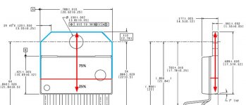
Wondering myself to what degree this assumption holds, I did an one-dimensional (1D) analysis of heat flow in the copper plate from the middle of the die to the tip of the mounting tab. Since modelling the heat transfer around the die is beyond the 1D anaysis, the model used places a line heat source across the middle of the tab (some 4.5mm from the connection pins). The heat source stretches across the copper plate width, and is assumed to send 75% of the heat the die produces towards the mounting tab tip. The remaining 25% of the heat produced by the die is dissipated by the remaining 25% of the copper area (see sketch). The copper plate length along the 75% arrow line is then 13.5mm (all dimensions measured with a digital slide caliper).
Modelling the problem of one dimensional conduction heat transfer (HT) with simultaneous heat rejection along the plate length leads to a first-order differential equation, the solution of which requires the so-called boundary conditions. In this case, these reduce to zero heat flow through the upper part of the package, the sides and the tab tip, which means that the heat is removed only from the bottom surface of the package through the 0.5mm thick epoxy layer with thermal conductivity of 1.3 W/(m x K), as in my note. The boundary condition at the heat source is represented by constant temperature.
The solution of the HT diff. eq. gives temperature distribution in terms of hyperbolic trig functions, which I'm not going to discuss here (it can be looked up in any good HT textbook). I implemented the solution in a short Matlab routine that plots the temperature distribution along the path, and calculates the amount of heat transferred.
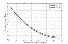
The red line in the diagram enclosed shows the temperature profile for the heat source temperature of 85 Deg.C; the temperature drop along the path is 18K. The amount of heat transferred in this direction is 30.2W, giving the total package dissipation of 40.3W which, with an Rth of 2K/W for the plastic package results in a die temperature of 105.6 deg.C (the heat sink is at 25 deg.C).
Letting now, for the fun of it, the sides of the package (the blue line in the package sketch) also exhange heat with the heat sink (e.g. by milling the package into the sink), and assuming 2.5mm of epoxy between the copper bar and the heat sink (the same as in my note, i.e. a conservative asumption), increases the equivalent thermal conductivity at the bottom from 1.3 to 1.36 W/(m x K). The blue line in the temperature plot shows the temp. distribution in that case, and the resulting heat transfer rate is 31.5W (a plus of 4.3%, which is almost the same as the conductivity increase).
BTW, using the Rth value for this part of the copper plate of 1.64 K/W, the temperature difference required to produce a heat flow of 30.2W is 50K, leading to the mean copper plate temperature of 75 Deg.C, which can easily be seen to fit the temperature distribution in the plot below. Not bad for a simple isothermal model.
So I don't see the prediction made above being fullfilled in this case.
This is as far as the analysis with simple means goes. I guess that the model John Escallier presented in Linear Audio Vol. 9 (I only started reading it on the train last night) could, given the data, provide more information. Further than that, there are Finite Element programs (e.g. Ansys, but given the data, too), and measurements.
Regards
Attachments
Very informative thread! Nice. Thnks to Tom, AndrewT & others. My experience with 4ohm load wasn't good...maybe because small heatsink. At full output power(60+) within 25-30min of time SPIKE protection circuitry kicks in!
krrrrrrrrrr.....�� but later i solved it with thick aluminium bar & active cooling. For my next build i am going to use 8ohm speakers. i know that lm3886 is capable of max 60-65wRMS into 8ohm load, but my speakers are 120watt rated �� Any impact on performance?
krrrrrrrrrr.....�� but later i solved it with thick aluminium bar & active cooling. For my next build i am going to use 8ohm speakers. i know that lm3886 is capable of max 60-65wRMS into 8ohm load, but my speakers are 120watt rated �� Any impact on performance?
A single LM3886 may be hard pressed to get to 65 W into 8 Ω, but two in parallel will do it.
Tom
Thnks Tom for you kind reply. if 'you' think so..then yes.
i just want to know that do you think a monoblock can handle 120wRMS 8r driver without effecting sound quality?
i don't want that much power, 60watt/ch is enough for me.

i just want to know that do you think a monoblock can handle 120wRMS 8r driver without effecting sound quality?
i don't want that much power, 60watt/ch is enough for me.
I don't see a problem driving a 120 W rated speaker with a 60 W amp.
Tom
I don't see a problem driving a 120 W rated speaker with a 60 W amp.
Tom
Alright. I bought a pair of 4ohm speakers today.
100watt rated.
- Status
- This old topic is closed. If you want to reopen this topic, contact a moderator using the "Report Post" button.
- Home
- Amplifiers
- Chip Amps
- LM3886 Thermal Experiment (with data)