It is well known that the GainCard amp started a new trend in diy circles and many tried to copy the design, if not the chassis construction then at least the circuitry. My first amp was also very much influenced by the Card and I thought initially that this is as far as one could go with the design.
However, after experimenting with different chassis built and more esoteric construction methods, it seems like the original concept can be further improved. After the controversy thread on AA, I was also bugged by Yoshi Segoshi of Sakura Systems to come up with something more original than merely a copy of the 47Labs amp and to create a Patek of GC amps, while Gaincard would still be a Rolex.😉
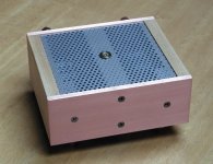
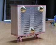
So here's my attempt at Patek amp. It uses similar size as Card, but it's slightly higher. I know it doesn't look very sexy, but the main concern was to achieve the mastery in the sound and not in the looks.
However, after experimenting with different chassis built and more esoteric construction methods, it seems like the original concept can be further improved. After the controversy thread on AA, I was also bugged by Yoshi Segoshi of Sakura Systems to come up with something more original than merely a copy of the 47Labs amp and to create a Patek of GC amps, while Gaincard would still be a Rolex.😉
So here's my attempt at Patek amp. It uses similar size as Card, but it's slightly higher. I know it doesn't look very sexy, but the main concern was to achieve the mastery in the sound and not in the looks.
Attachments
I always listen to a good advice and also this time a quote from Thorsten gave some ideas for a new approach:
So I decided on the best materials I could use in such design and the core of the amp, the main support bar, is made out of bronze, while the front and back is out of 1/4" copper flat bars and "I keep the wood" so the sides are made of maple.
The size is about 5" x 6" and it's 2.5" high (excluding spikes)
Kuei Yang Wang said:Well, I HATE (not) to say it, but you may wish to read my original comments on CFrasers Gainclone "Builder Data" Page... Look for "Thorstens Thoughts"....
http://home.ca.inter.net/~cfraser/Gainbuilder.htm
What I would suggest as Heatsink in such a design is actually a block of Bronze with several chimeys drilled out.
Keep the wood and C37 Lacquer it. And probably some Altman "Tubolator" Lacquer on the Chip and C37 on all Capacitors, plus wooden, C37 lacquered Capacitor Clamps for the (plastic stripped) PSU Cap's. Oh yes, also avoid any magnetic screws....
So I decided on the best materials I could use in such design and the core of the amp, the main support bar, is made out of bronze, while the front and back is out of 1/4" copper flat bars and "I keep the wood" so the sides are made of maple.
The size is about 5" x 6" and it's 2.5" high (excluding spikes)
Attachments
EDIT: I was too fast, insights are coming in...!
Hi!
But in what ways does it differ exactly from the original GC concept, or the "improved inverted GC concept" developed by you and members of this forum?
Don't just show off you chassis building capabilities 😉 , offer some insights!
Circuitry? Chip (do I dare to ask? I assume that the LM3875 is still being used on this one)? 😕
Shed some light!
Bye,
Arndt
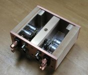
I didn't drill the convection channels through bronze slab, as from my experience the GC doesn't normally run that hot and I preferred to use top and bottom covers for a complete look. Here I used a perforated, ultralight aluminum panels. They shouldn't affect the sound in any way, as I know from other members, that this may be problematic. Their surface also helps to dissipate more heat and the holes keep the inside cooler. As usually, i'm using those brass spikes, as I get them pretty cheap and they sound good. One spike in a back, right in a place where the chips are mounted.
Attachments
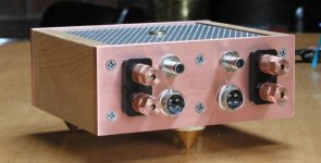
The rear panel is pretty straightforward and the only upgrade from my usual stuff are Kimber RCA jacks. I didn't implement volume control in this amp, as I want to use it as two channel monoblock for bi-amped system.
For stereo operation, I will come up with a support platform, containing PS and volume control with source switcher. I want to be more original this time😉 and don't want to lower the amp's performance with a standard plastic pot.
Also titanium, aircraft screws are used.
For stereo operation, I will come up with a support platform, containing PS and volume control with source switcher. I want to be more original this time😉 and don't want to lower the amp's performance with a standard plastic pot.
Also titanium, aircraft screws are used.
Attachments
What is the small input cap you use? Not the BG you used in your amps before, but what else?
I like the approach of using more wood. Even if it means using some additional shielding material. For a cheaper approach I just used on an amp of mine some oak shielded with cheap PCB material (those PCB-material meant for etching your own boards, just without etching).
Wood is great. Even I can work on it 😉 I've got two left hands when it comes to metalworks.
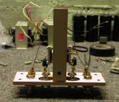
But what I also like is the concept of using a thick metal bar in the middle of the amp. Never thought pf that before (normally everybody attaches power devices to the "outside walls" of an amp, with inverted symmetry for stereo amps. This approach is nice....
I like the approach of using more wood. Even if it means using some additional shielding material. For a cheaper approach I just used on an amp of mine some oak shielded with cheap PCB material (those PCB-material meant for etching your own boards, just without etching).
Wood is great. Even I can work on it 😉 I've got two left hands when it comes to metalworks.
But what I also like is the concept of using a thick metal bar in the middle of the amp. Never thought pf that before (normally everybody attaches power devices to the "outside walls" of an amp, with inverted symmetry for stereo amps. This approach is nice....
Coming back to Thorsten quote:
I will also be using batteries and TVC's with this amp, so basically your wishlist is fulfilled. The only thing missing is C37 laquer, but this you could do yourself, when playing with the amp.
And if you would decide on a review, there shouldn't be any confilct of interests, as this amp is non inverting😉
Jokes aside, thanks for good suggestions.
Kuei Yang Wang said:
And then change the external Powerpack to 4 X 12V/7AH++ SLA Batteries, plus charger. Oh, and fit Autoformer TVC's as Volume controls.
Now THAT would likely be an Amplifier I'd just LOVE to test for an extended period for you.... 😉
Sayonara
I will also be using batteries and TVC's with this amp, so basically your wishlist is fulfilled. The only thing missing is C37 laquer, but this you could do yourself, when playing with the amp.
And if you would decide on a review, there shouldn't be any confilct of interests, as this amp is non inverting😉
Jokes aside, thanks for good suggestions.
Cradle22 said:What is the small input cap you use? Not the BG you used in your amps before, but what else?
I like the approach of using more wood. Even if it means using some additional shielding material. For a cheaper approach I just used on an amp of mine some oak shielded with cheap PCB material (those PCB-material meant for etching your own boards, just without etching).
Wood is great. Even I can work on it 😉 I've got two left hands when it comes to metalworks.
But what I also like is the concept of using a thick metal bar in the middle of the amp. Never thought pf that before (normally everybody attaches power devices to the "outside walls" of an amp, with inverted symmetry for stereo amps. This approach is nice....
IMHO, this approch is so far the best for that type of amp. Since I didn't want to copy 47Labs this time, the concept of center bar divides the amp again into halfs and seem to be better from resonance control view. Instead of bronze one can use copper and the front and rear panels could be made out of standard, preanodized, 1/8" bars available from HD. The wood adds a nice touch and works as capacitors support as well. This amp's character borrows more from tube equipment chassis materials and it can also be observed in its sound. It doesn't posses this aluminum glare and the silence between notes seem to be deeper. It is very smooth sounding right from the beginning. And for proper performance those BG need at least 24 hours.
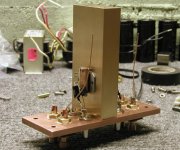
I'm not using any small coupling caps. Signal goes directly through 244 ohm Vishay to + input. Feedback is 22k Caddock, another 22k vishay from + to ground and temporarily (for lack of anything better around) 655ohm Holco setting the gain.
This is jewellery!! 🙂
The colours of all different materials fit so well together. 😎
I never did the effort to listen to differences between materials and certainly not the way you do.
How can one describe the sound of rosewood and maple in conjunction with bronze, copper and silver?
Only two possibilities: One must have extremely good ears or the perception is the main factor. Just guessing.
You must have both of them and clearly also the skills to build those extremely beautiful amps.
When you describe those different materials sound-wise, you must have compared them to each other and other materials as well. Which I know you did for most of the electronic parts. But now also the case parts?
This is astonishingly nice.
Oh, and make sure the mains cables are well burnt in before testing (Just couldn’t resist 😉 )
/Hugo 🙂
The colours of all different materials fit so well together. 😎
I never did the effort to listen to differences between materials and certainly not the way you do.
How can one describe the sound of rosewood and maple in conjunction with bronze, copper and silver?
Only two possibilities: One must have extremely good ears or the perception is the main factor. Just guessing.
You must have both of them and clearly also the skills to build those extremely beautiful amps.
When you describe those different materials sound-wise, you must have compared them to each other and other materials as well. Which I know you did for most of the electronic parts. But now also the case parts?
This is astonishingly nice.
Oh, and make sure the mains cables are well burnt in before testing
(Just couldn’t resist 😉 )/Hugo 🙂
Great Work Peter!!!
Hey,paint it with dammar at least (if you don't have C37).
you can get it at every artist's store.
Bartek
Hey,paint it with dammar at least (if you don't have C37).
you can get it at every artist's store.
Bartek
Peter, there is a cap. on the picture in post #4.What is it's purpose?
You say there is no input cap ,maybe that's Zobel from the output to ground?
Bartek
You say there is no input cap ,maybe that's Zobel from the output to ground?
Bartek
Very, very nice work Peter!
Just wanted to mention that several people using battery clones reported best results using film caps ~10uf(or less) for rail bypass when using batteries.
Scott
I will also be using batteries
Just wanted to mention that several people using battery clones reported best results using film caps ~10uf(or less) for rail bypass when using batteries.
Scott
I switched to batteries now, and although I said in the other thread that I wasn't impressed that much, after listening again for a while, I have to admit that there is something to the sound of the amp running on batteries. It sounds like nothing else and the music seems to be very effortless. The detail is improved and everything seems to be harmonically right and coherent. The effect similar to using an air suspention platform. Nothing really to complain about. Also, the bass is deeper.
I just listened to The Wall CD (the first one) and on track 10, 50 sec into it, a girl says "Hello". Right after that there is an echoing voice in left channel saying "Hello" again, sort of washed out with the music. I've never noticed it before. If Combat 84 will sound as good as well, I think I will switch to batteries permanently😉
I noticed that sometimes TVC seems to sound a bit dull (in the highs) on certain recordings, but with this amp it works fine on everything. Mind you, the BG are not even recharged completely yet😉
OK guys, even though i am an old time speaker builder i have no idea what C37 is?Is its purpose to dampen vibrations?
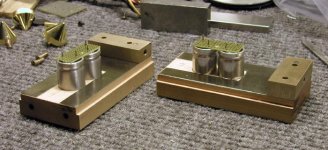
Hay Peter is the hold down bar on the chips Cu, brass???I played around and finally(as finally as anything i do LOL) settled on Poly but am always open to suggestions.
ron
BTW! Peter, good engineering. Form follows function.Like the center H/S and good flow.
Hay Peter is the hold down bar on the chips Cu, brass???I played around and finally(as finally as anything i do LOL) settled on Poly but am always open to suggestions.
ron
BTW! Peter, good engineering. Form follows function.Like the center H/S and good flow.

Hey jam, get me a gun and I'll shoot you😉
The bar on the chip is copper. I didn't experiment with that, but since it worked on monoblocks I decided on same approach here. I like the shielding properties of copper, and I wanted to use natural materials, not man-made😉
I'm not sure about C37, but I presume it's a sort of violin laquer improving the sound, but I've never tried it yet. Do google search, you'll find enough info.
I played whole evening using batteries and I think I start to like them. Lyrics seem to be much easier to uderstand, especially for someone who's listening to all sorts of music😉
But I still don't feel that comfortable with batteries. What happens after they run out of voltage (unevenly)? Any DC offset danger?
Since I'm using 2 of them in series, I have to figure out a convenient way to charge. I think they could be charged in series as well, by 24V charger?
New amp, TVC and batteries seem like a winning combination. Kuei was right....
- Status
- Not open for further replies.
- Home
- Amplifiers
- Chip Amps
- Trying to improve on a GainCard concept