Thanks Carlosfm
Maybe ,but with amp connected to preamp there is absolutely no hum in the speakers (usually in case of loops there is).
Also I converted the IGC to NIGC without changing grounding schem. and IGC didn't have that noise.
I will try one channel later (I have to go out ,now)
Bartek
Maybe ,but with amp connected to preamp there is absolutely no hum in the speakers (usually in case of loops there is).
Also I converted the IGC to NIGC without changing grounding schem. and IGC didn't have that noise.
I will try one channel later (I have to go out ,now)
Bartek
Bartek,
What's your exact schematic?
"Just half an hour ago I checked everything once again.
I put that 220ohm resistor in series with + input and I think I leave it there becouse it seems not to change the sound (opposite than with putting input coupling cap)."
I hope you ment (and you used) 220 kOhm rather 220 Ohm.
Hi!
That made me wonder... I have read about stuff like this before, and also experienced it by myself on my GC stuff.
If it comes to actually manufacturing something like the LM3875 or OPA 549... I think the process could be compared to manufacturing a computers processor.
And from those I know that for example position of the die for each chip on the big wafer, and also experience in building that particular chip matters in terms of quality of the resulting processor (for example, the frequency with which it can be run).
And we all know of transistors having different measurements (therefore the "matching" of output & input transistors).
😕 😕 😕 😕 😕 😕
And so I just wondrered: Has anyone ever experienced sonic differences / variations because of those manufacturing processes?
Would it be advisable to "match" / measure chips used for GCs?
Bye,
Arndt
Peter Daniel said:I once had a chip which in particualr NI setup produced 400mV (no 22k to ground) and when I replaced it with the other one, I got 170mV of offset.
That made me wonder... I have read about stuff like this before, and also experienced it by myself on my GC stuff.
If it comes to actually manufacturing something like the LM3875 or OPA 549... I think the process could be compared to manufacturing a computers processor.
And from those I know that for example position of the die for each chip on the big wafer, and also experience in building that particular chip matters in terms of quality of the resulting processor (for example, the frequency with which it can be run).
And we all know of transistors having different measurements (therefore the "matching" of output & input transistors).
😕 😕 😕 😕 😕 😕
And so I just wondrered: Has anyone ever experienced sonic differences / variations because of those manufacturing processes?
Would it be advisable to "match" / measure chips used for GCs?
Bye,
Arndt
Here's a simple charger that disconnects AC while playing...
Rod Elliot of ESP has provided an easy design that does it all.
Introduction
For those who want the cleanest possible DC for sensitive preamps, battery power is ideal. At last, remembering to turn the charger back on is no longer a problem!
This project is one for the experimenter, but as shown will work extremely well. The sensing circuit can be made so sensitive that a load of only 2.5mA is enough for the circuit to detect, and disconnect the charger.
The idea is that the charger is left permanently connected, but of course that would normally introduce some hum into the supply lines. The sensor detects that you have switched on the preamp (or small power amp for that matter), and immediately switches off the charger, so while listening, there is no connection to the AC. Although it is possible to use a "solid state" switch, these are not as good as a standard relay, which provides perfect isolation of the AC input.
Elliot Charger
material choice
I often wonder if the choice of case materials isn't just as important as the dimensions and shape of the case. After all resonance behaviour is controlled by both the dimension/shape choices as well as sound velocity of the medium.
To that effect, the position of the amp chip on the bar would matter eg. centered vs. off-centered, as well as the size and material of the screws, torque (of course), shape of the "bar" (eg. a disk, or cylindre vs. a rectangular bar) etc.
I also wonder what it would sound like (in this implementation) if the wooden sides were eliminated and the thin perf. aluminium was used there instead - ie. an overall simpler design more akin to that of a tuning fork with possibly a stronger sonic character but better ?
Going along this (even more expensive experimental) route I would be tempted to try and subjectively correlate the amps sound with that of the case when eg. knocking on it or performing some other sonic test on it.
Perhaps instrument builders would have more to say on these matters.
Well this approach would probably lead us fast in the region of diminishing returns and would be quite impossible to pursue without some quantitative research done first and a method established with the aid of suitable software for example (Excel, or other freeware).
Lastly I noticed here a switch to magnet wire for the internal wiring - this is sth I've "decided" to use as well on the second amp I'm making (more a result of having nothing else available actually) and I'm wondering what the difference will be.
Stelios
Peter,
you make delicious little pakages that look almost good to eat but I think it's time to break through the glass ceiling which you have quite obviously reached.
I.E. It's time to try a better circuit dude!
you make delicious little pakages that look almost good to eat but I think it's time to break through the glass ceiling which you have quite obviously reached.
I.E. It's time to try a better circuit dude!
tbla said:...very tastefull peter, mail me an offer - only the amp and not the ext trafo....🙂
You understand that just 4 electrolytics are about $300?😉
4 electrolytics are about $300
...and people say that my prices are too high....😀
ok, i'll take the empty box incl. the cardas b posts.....
btw how come you don't use cardas rca femaleplug...?
Because Kimber is more expensive and I kept them for special occasions. I'm not that sure about it, but whenever I tried Cardas it seemed to add very soft character. Sometimes I think that Chinese (tiffany knock offs) are simply better.
I'll be building few more boxes with copper inside and aluminum on the outside. I could offer them for sale then. They will also be slightly lower (2" vs. 2.5") for better looks.
I'll be building few more boxes with copper inside and aluminum on the outside. I could offer them for sale then. They will also be slightly lower (2" vs. 2.5") for better looks.
tried Cardas it seemed to add very soft character.
My experience exactly. I still like them but wouldn't mind something with slightly less euphonic character. Any suggestions?
Also I converted the IGC to NIGC without changing grounding schem. and IGC didn't have that noise.
The IGC is inherently more stable so it's quite possible after the conversion you get oscillations.
Excel, or other freeware
Oh, me God! Hope that Gates dude isn't cruising the forums looking for an amp to build.
analog_sa said:
Oh, me God! Hope that Gates dude isn't cruising the forums looking for an amp to build.
The new version of windows comes with an amp built in {it's called "winamp"}. It will be an amp better than any other amp before it (until the next windows upgrade that is).
analog_sa said:
My experience exactly. I still like them but wouldn't mind something with slightly less euphonic character. Any suggestions?
Normally I use those Chinese Tiffany imitations, I buy at $2.5, and they seem to sound not that bad. Otherwise, Kimber seems to be fine, but it's quite expensive ( $26). I understand that plating on Kimber is thicker and it also seems to be very tight when attaching male connectors.
stelios said:I often wonder if the choice of case materials isn't just as important as the dimensions and shape of the case. After all resonance behaviour is controlled by both the dimension/shape choices as well as sound velocity of the medium.
To that effect, the position of the amp chip on the bar would matter eg. centered vs. off-centered, as well as the size and material of the screws, torque (of course), shape of the "bar" (eg. a disk, or cylindre vs. a rectangular bar) etc.
I also wonder what it would sound like (in this implementation) if the wooden sides were eliminated and the thin perf. aluminium was used there instead - ie. an overall simpler design more akin to that of a tuning fork with possibly a stronger sonic character but better ?
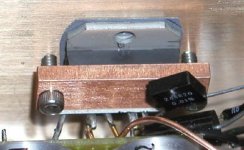
I would imagine that in my case the most critical area is the barr attaching chip to the chassis. I didn't experiment with that, but both the material and the torque on the screws certainly affects the chip (I'm cautious enough not to say sound😉. I used the minimum torque on my screwdriver to be safe.
Attachments
Peter Daniel said:
I would imagine that in my case the most critical area is the barr attaching chip to the chassis. I didn't experiment with that, but both the material and the torque on the screws certainly affects the chip (I'm cautious enough not to say sound😉. I used the minimum torque on my screwdriver to be safe.
I remember a while ago you were posting about the differences between insulating pads. So I thought different torque settings will have different damping effects. I guess after a certain point the amp would sound rather strained 😉 (Btw what are these pads in this picture ? Did you cut them from a larger sheet ?)
Anyway, my whole post was generated from a thought I had yesterday while I was deliberating how I would cut sections from some pi-shaped aluminium extrusion off-cuts I had lying around to optimally built the sides of a box based on a large heatsink. While doing that I was flicking them with my fingers to get that 'ping' sound and noticed they sounded different.
And the rest as they say is history... (or, in this case, maybe it isn't 😉)
Well.. migth be time to try a amp not so sensitive to just about everything?...aaaagh why are you chasing me with tar and feathers =)
Is there any successor to the LM3875 from Linear themselfs on the horizon?
/ micke
Is there any successor to the LM3875 from Linear themselfs on the horizon?
/ micke
Those are silpads and I cut them from TO-3 insulator.
I don't think there are non-sensitive amps. I was experimenting with Aleph and the material used under the feet made very big difference as well.
I don't think there are non-sensitive amps. I was experimenting with Aleph and the material used under the feet made very big difference as well.
Peter Daniel said:
I would imagine that in my case the most critical area is the barr attaching chip to the chassis. I didn't experiment with that, but both the material and the torque on the screws certainly affects the chip (I'm cautious enough not to say sound😉. I used the minimum torque on my screwdriver to be safe.
Peter,
I'm sure you thought about it, but I'll mention it anyway.
I'm not too crazy about that kind of attachemen to the heat sink as the chip starts heating up the plastic will start expanding and ..... crack. And if not "crack" at least a lot more compression on the chip inside. Unles you have some kind of spring-loading construction.
Greg
- Status
- Not open for further replies.
- Home
- Amplifiers
- Chip Amps
- Trying to improve on a GainCard concept