SOUNDSTREAM OLD SCHOOL AMPLIFIERS
Hello, my name is Wade Stewart. I am the engineer that designed and manufactured all of the Old School Soundstream amplifiers and crossovers from 1981 through 1998, all REFERENCE, CLASS A’S and old RUBICON amps. I am here for any discussions, questions or any other need you may have concerning old school Soundstream amps and crossovers. I also offer Schematics, Owners Manuals and Repair of any older Soundstream amps.
Hello, my name is Wade Stewart. I am the engineer that designed and manufactured all of the Old School Soundstream amplifiers and crossovers from 1981 through 1998, all REFERENCE, CLASS A’S and old RUBICON amps. I am here for any discussions, questions or any other need you may have concerning old school Soundstream amps and crossovers. I also offer Schematics, Owners Manuals and Repair of any older Soundstream amps.
Last edited:
If you don't get any questions now, you may want to bump the thread until users get to know your user name better.
I have a question but I'd refer to ask it off of the forum. If you don't mind, email me.
babin_perry@yahoo.com
I have a question but I'd refer to ask it off of the forum. If you don't mind, email me.
babin_perry@yahoo.com
Hi and welcome to the forum!!
Let me start off by saying the D60 and D100's were some of my favorite amps. (never had the D200)
So my question is:
I read earlier that the D series amps were a "cleaned up(layout wise)" version of a design Nelson did. Is that true?
Also is it also true that the only issue with the amps were the ratings only spec'ed power supplies? Can anything be done with the factory D series amp to provide more margin in the power supply?
I absolutely loved the Class A and Reference series amps. These were the smoothest sounding amps on the market.
troystg, The original D60, D100, D200, CA40 and CA50 were designed by Nelson Pass. they had two problems. 1. They were laid out with point to point wiring which meant that they were not cost effective to build. 2. They all had thermal run away. A condition where the bias is set to high and over time the amps would overheat and shut down. All I did tto solve this problem was to re-adjust the bias to a lower setting.Hi and welcome to the forum!!
Let me start off by saying the D60 and D100's were some of my favorite amps. (never had the D200)
So my question is:
I read earlier that the D series amps were a "cleaned up(layout wise)" version of a design Nelson did. Is that true?
Also is it also true that the only issue with the amps were the ratings only spec'ed power supplies? Can anything be done with the factory D series amp to provide more margin in the power supply?
In the II series I re-laid them out on single PC Boards, then my company began manufacturing them. I also added the CA100 an adaptation based on Nelsons original designs.
Could you give me a clearer description of exactly waht you mean when you asked. Also is it also true that the only issue with the amps were the ratings only spec'ed power supplies? Are you talking about thgere power ratings? Can anything be done with the factory D series amp to provide more margin in the power supply? Are you asking if you can get more power out of thge amps by modifying the power supplies?
I designed the MC series, Reference series, the later CA series, Granite, uSA and SA series. These were designs of my own. I also designed all heat sinks, power and output connectors and rca input jacks. I also designed the tarantula and Davinci. I had a Pro Audio brand named Stewart electronics. The tarantula was based on Pro amp that was part of Stewart World Series amplifier line. 7 amplifiers from 125 watts x 2. To 2000 watts x 2.
Give me a better description of what you were asking and i will answer you. If youi or anyone else has any more questions please feel free to contact me. I have Scematics and owners Manuals. I can send them to you. I also can repair any Soundstream Old Ochool and Rubicon amps.
Thanks,
wadest
Hi Wadest-
I will try to clarify..
In the rare occasion I have seen or heard of the D60 and 100 failing it was generally the power supply that went out. However in every instance they were using it beyond the rated output or below the minimum impedance allowed so it was not a "fault" of the amp. I was wondering if there was a way to beef up the supply a tad to make it a little more robust in case it is pushed beyond it's specifications.. Because they do sound fabulous and I have a tendency to turn it up a bit more than I should.
And thank you so much for making incredible amps!!!!
troystg, Those amps were originally designed by nelson Pass. They used a dynamic supply, no clock chip. The design relyed lly on the imbalance between the switching transistors to make it work. In theory one side would always start before the other and start it switching. if you connect it to a power supply and slowely bring it up from zero the supply will blow up every time. the D100 used two 25 Amp transistors per side. I just looked and the only transistors I found in those or similar packages were 30 Amps. I was hired originally to make those amps manufacturable because the original amps required point to point wiring. The first amps designed by me were the MC series which all used a clock chip.
sorry I didn't get back tgo you right away but I lost my wi-fi connection.
wadest
sorry I didn't get back tgo you right away but I lost my wi-fi connection.
wadest
Soundstream
Pretty much all Soundstream amps using Darlington output devices will fail if biased "correctly". The TIP142/147 and the TIP102/107 have serious thermal issues.
If these devices are biased with the Vbe generator set to 2.25v (A good value when a double Darlington DISCRTETE pair of devices are used) they will blow up.
Soundstream finally discovered that using 1 ohm emitter resistors and high speed bypass diodes solved the issue of thermal runaway.
The 0.27 ohm emitter resistors used in almost all Soundstream amplifiers are too low in value to control the Darlington's idling current if the bias generator is set correctly.
Every Soundstream amplifier we repair, we change the emitter parts to 1 ohm + diode, set the Vbe multiplier correctly and they do not blow up.
Similar issue with the paralleling of the FEP16/FEN16 diodes, no current sharing resistor and we see these diodes bad all the time.
MOER, I never designed any amps using the TIP142/TIP147. Those were used by the engineer that designed the Rubicon series. I'm guessing he switched to them because they were higher current devices. But he never looked at the Safe Operating Area. The TIP102/TIP107 have a much better SOA rating. Especially if you put a filter in limitimg them to 100 ms, This information was determined by getting a SAO chart from the manufaturers, Motorola and TI, showing operation to 100ms, which increased the sOA to about 1.4x. You could actually get away with less devices for the same power level. Usung these devices we built over 120.000 amplifiers in 17 years, and we did not have any failure problems. Our failure rate was between 1% to 2%. Pretty impressive when you realize that the Reference series were designed to operate into 1/2 ohm per channel.
As far as the bias goes all amplifiers were adjusted in the lab to just above the appearance of crossover distortion not at a predetermined voltage. Every time we had to switch devices to another production run we would double check the bias.
The emitter resistors we used worked fine. The 1 ohm with the parralell diodes was used in the Class A amplifiers. At low power the bias was higher than normal. so the amplifier were working as ifv they were running in Class A mode. At higher power levels the amps operated in Class AB mode.
We parralelled the rectifiers only after derating them to 80% of there full rating. This was done at the suggestion of the devices manufacturers.
wadest
Last edited:

Still have to take the RUB1000-2 apart to trace out the FEB's.
On the way home today I measured the temp of the heat-sink on the Ref 500. At a moderate level and in about 5 minutes, the temp went to 160 deg. (71Cel).
On the way home today I measured the temp of the heat-sink on the Ref 500. At a moderate level and in about 5 minutes, the temp went to 160 deg. (71Cel).
amps
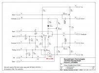
90scaraudio, The ref 500 seems like it's running awfully hot. you said it was running at a moderate level. is that aloud or just listening moderate? IAttached to this message i have included schematics for Rubicon 1002. it should be the same as the 1000-2 e3xcept for two more mosftes. i think we already went over this. I'm also including the schematics for 500 and thr rubicon FEB in case you need them. let me know what happens.
90scaraudio, The ref 500 seems like it's running awfully hot. you said it was running at a moderate level. is that aloud or just listening moderate? IAttached to this message i have included schematics for Rubicon 1002. it should be the same as the 1000-2 e3xcept for two more mosftes. i think we already went over this. I'm also including the schematics for 500 and thr rubicon FEB in case you need them. let me know what happens.
Attachments
Welcome Wade. I was wondering if you could send me an e-mail. I had a couple questions to run by you. Thanks Rick
rickclk1@gmail.com
rickclk1@gmail.com
Wade... I pulled one of the FEB that came with the RUB1000-2, (Factory stock) and compared it, pin by pin, and resistor measurements to the 4 new boards I bought.
Here's what I found....
Your correct, they are the same. There is one difference, the 2SA1479 (Q4) and 2SC3789 (Q5) that are on the new FEB's I bought and the FEB's on the RUB1000-2 are different. These have 2SA1381 (Q4) and 2SC3503 (Q5) installed.
The problem I had with one channel clipping when I put in the new FEB's was out of the 4 I bought, one of them has a different value resistor inserted at R4.
Figures that I just had to use 1 of the 4 that would cause me stress 😱.
R4 should be a 806K. The one that caused the problem measured 1.33K 😕
Attachments
- Home
- General Interest
- Car Audio
- Soundstream old school amplifiers