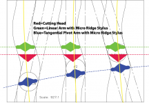
Is there a misspelling? The Blue figures should be equal to "Pivot Arm with Micro Ridge Stylus" as the blue dotted line travel across in an arc, which is what a traditional pivot arm does. There's nothing tangential about it.
It is not a misspelling. First, the drawing may not be precise. I tried to avoid the word, tangent because once you use the word, tangent, you are implying there is an imagined line that travels through the middle of small waveforms. These imagined lines are yellow in the new drawing. All the blue stylus are tangent to yellow lines. But in Ralf's reasoning, the stylus can't be tangent to the groove because the groove is a series of small waveforms. The blue dot line is Thales circle.
Attachments
Last edited:
The blue dot line is Thales circle.
Any ARTICULATED tonearm based on the Thales circle should line up just like any parallel tracker or the cutting head. The whole point of this type of tonearms is to track like a linear tonearm. The diagram suggests there's gross tracking error. Sorry, this doesn't make sense at all.
Any ARTICULATED tonearm based on the Thales circle should line up just like any parallel tracker or the cutting head. The whole point of this type of tonearms is to track like a linear tonearm.
I agree. As I said, the diagram may not be precise since I put emphasis on the waveforms and I also added a comment that the blue stylus is tangent to the yellow lines to avoid any misunderstandings.
I posted somewhere that best would be to have been a pivoted cutting lathe same as standard 9 inch tonearm. Kind of like a cutting lathe mimicking 9 inch standard pivot tonearm. Not impossible in modern times I think.the cutterhead stylus is tangential to the modulated signal being cut, not the groove spiral.
Regards
9" vs 12"
9 inches might be too short. Notice almost all tonearms mounted next to the cutting lathe platter are 12" arms like Ortofon or SME 3012? It's because all those platters are 16" in diameter to accommodate all record sizes. 9 inch arm would be too tight or not enough clearance for the cutting head arm to maneuver. I agree that 9 inches would be ideal. Too late now!
Even if cut with no overhang, it would still have skating force for the passive tonearm though. Well, it will be less headache than conventional geometry.
best would be to have been a pivoted cutting lathe same as standard 9 inch tonearm. Kind of like a cutting lathe mimicking 9 inch standard pivot tonearm. Not impossible in modern times I think.
9 inches might be too short. Notice almost all tonearms mounted next to the cutting lathe platter are 12" arms like Ortofon or SME 3012? It's because all those platters are 16" in diameter to accommodate all record sizes. 9 inch arm would be too tight or not enough clearance for the cutting head arm to maneuver. I agree that 9 inches would be ideal. Too late now!
Even if cut with no overhang, it would still have skating force for the passive tonearm though. Well, it will be less headache than conventional geometry.
Last edited:
Can you explain what you mean by "tangential pivot arm"
This thread covers almost everything about the genre with 10 years worth of material to read!
Angling for 90° - tangential pivot tonearms
Yes forgot the lathe platter are large.9 inches might be too short. Notice almost all tonearms mounted next to the cutting lathe platter are 12" arms like Ortofon or SME 3012? It's because all those platters are 16" in diameter to accommodate all record sizes. 9 inch arm would be too tight or not enough clearance for the cutting head arm to maneuver. I agree that 9 inches would be ideal. Too late now!
Even if cut with no overhang, it would still have skating force for the passive tonearm though. Well, it will be less headache than conventional geometry.
Regards
")
Yes, a single-pivot tonearm would need to be infinitely long, as per Euclid's axioms.
Hi ejp,
My post was not about tone arms. I tried to show that the phrase "tracking tangentially to the groove" is a colloquialism and not an accurate description of what happens when the stylus interacts with a groove.
I read up on Euclid a little bit. He made some profoundly amazing observations:
"A line can be drawn from a point to any other point.
A finite line can be extended indefinitely.
A circle can be drawn, given a center and a radius.
All right angles are ninety degrees"
Really?
ralf
Am I missing something, isn't this just justification for preferring elliptical or hyperelliptic stylus shapes? ie trying to match the cutter geometry better.
Hi Mark,
I used a conical stylus because it is easier to draw a circle than an ellipse.
If I had drawn an ellipse, the gross deviance from tangential tracking would not have changed.
The way I understand it, the use of an elliptical stylus prevents the signals of the left channel from being out of phase with the signals from the right channel. I heard someone calling it "time smear"
Sincerely,
ralf
Considering the fact that a cutter head is per definitionem tangential to the groove to be cut, I don't understand the problem with the tangential playback arms. Its tangentiality is controlled by the dragging force, i.e. no skating force is generated.
Hi Icsaszar,
I am not sure that I understand your post. Keep that in mind when reading my reply.
The cutter head consists of two big fat coils that are cooled by precious gas and can't be tangential to anything. When a cutting engineer sets up the groove cutter, he sets it up so that its cutting face is coplanar with a straight line that intersects the center line of the platter spindle otherwise known as the radius. A cross section of a typical groove cutter, when viewed looking straight down upon the lathe platter looks like an upside-down pyramid. If he wanted to set the cutting face of the groove cutter "tangential to the groove", where would he get the "groove"? Maybe from some of the LPs lying around in the studio? Which Lp to pick? Doc Watson? The Beatles? Jussie Smollet?
The dragging force and anti skating have NOTHING to do with my post.
Sincerely,
Ralf
Last edited:
You show the excursion due to the low frequency part of the signal. What does this prove regarding the tangent to the groove?
Hi alighiszem,
I got the picture of the groove at random off the Internet.
I have no idea if the groove represents low or high frequency content.
Due to the fact that the groove switches from side to side at the speed of audio frequencies, the stylus and the groove can never be tangent to each other.
Sincerely,
Ralf
Ralf, I mean the groove just being cut runs out from below the cutter edge so that it's tangent is perpendicular to the actual radius. Surely the axis of the cutter head is perpendicular to the actual radius, and the tangent of the groove at the cutter edge is along the line of the named axis.When a cutting engineer sets up the groove cutter, he sets it up so that its cutting face is coplanar with a straight line that intersects the center line of the platter spindle otherwise known as the radius.
If the playback stylus had the same shape as the cutter edge, and followed the same path with the same (zero) angle from the tangent, like an ideal LT system would do, there would not be any tracking angle error. I agree that stylus geometry (especially spherical) might cause phase error, but it is probably significant only at higher frequencies.
No it's not. The groove direction is that of the vector sum of the constant forward rotational velocity and the transverse modulation velocity. By the parallelogram law this is diagonal.Ralf, I mean the groove just being cut runs out from below the cutter edge so that it's tangent is perpendicular to the actual radius.
Which axis? The cutter head can move vertically and laterally and as explained above the groove direction is determined by the rotational velocity and lateral modulation.Surely the axis of the cutter head is perpendicular to the actual radius, and the tangent of the groove at the cutter edge is along the line of the named axis.
None of this makes any sense.If the playback stylus had the same shape as the cutter edge, and followed the same path with the same (zero) angle from the tangent, like an ideal LT system would do, there would not be any tracking angle error.
Actually it is more accurate to say it moves in two axes at ±45 degrees.The cutter head can move vertically and laterally
naive question
A cute can of worms - that can take us far, Ralf -
We all know, or believe ("Our LTA tracks like the lathe cut it " is a common claim) that the lathe acts parallel to the disc radius.
But only the carriage + coils or also the cutting tool, on both axis? Or is it mounted on a cantilever and moved by coils + magnet, mirroring our stylus tip behavior?
carlo
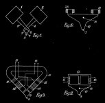
Blumlein patent - attachment
A cute can of worms - that can take us far, Ralf -
We all know, or believe ("Our LTA tracks like the lathe cut it " is a common claim) that the lathe acts parallel to the disc radius.
But only the carriage + coils or also the cutting tool, on both axis? Or is it mounted on a cantilever and moved by coils + magnet, mirroring our stylus tip behavior?
carlo
Blumlein patent - attachment
Attachments
Now I think I understand the problem. The arm follows the averaged path of the groove because of the low pass function defined by the arm+pickup effective mass and the cantilever compliance.
However, the stylus follows the groove modulation, where the cantilever moves on a sphere because the end of the suspension is fixed, however the cutting edge of lathe moves in the plane that intersects the radius.
Also the shape of the stylus is different from the cutting tool, so the point of contact moves to and fro depending of the modulation, especially at a spherical stylus.
Opening a different can of worms in off-topic-ville
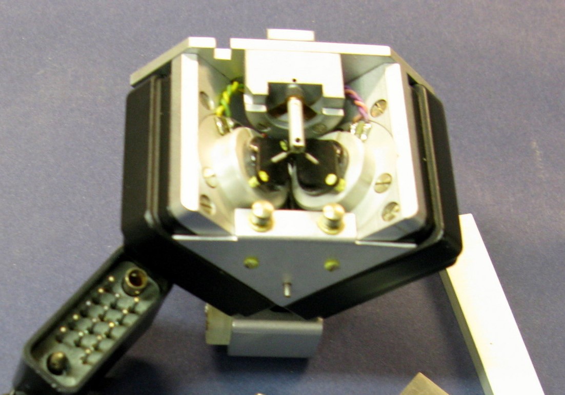
Have a look at these photos from my files. A Neumann cutterhead stylus is indeed mounted on a cantilever and is actuated by two coils, offset +/- 45 degrees. Here is a photo of a SX-68 that clearly shows the cantilever (with no stylus installed). The cantilever is anchored in a pivot or fulcrum and the stylus end is attached to the L & R coils:
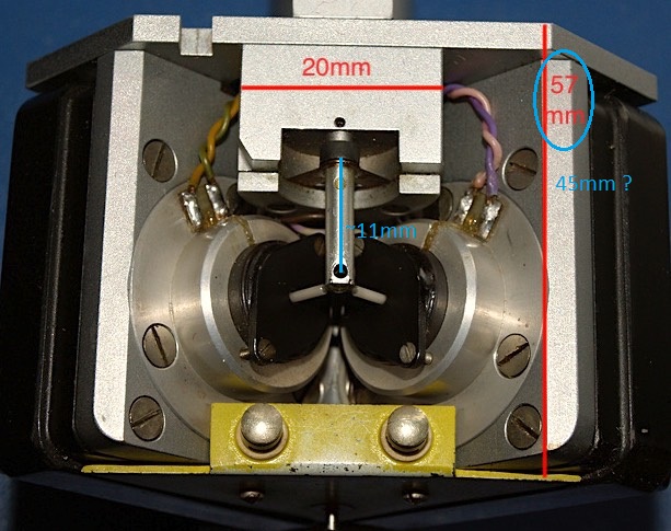
Next up is an undocumented photo that has some dimensions in red (not mine). It could be a SX-68 or maybe a SX-74, which is a newer version of the SX-68. I suspect that the dimension labeled “57 mm” in red is a typo since the Neumann spec sheet shows that dimension to be 45 mm. For the moment let’s neglect the error introduced by the photo having been taken slightly off-angle. The 20mm dimension appears to be about right.
If you scale the cantilever per the corrected dimensions, then the cantilever length works out to be about 11mm:
Here are the actual dimensions of a SX-74 from Neumann’s spec sheet:
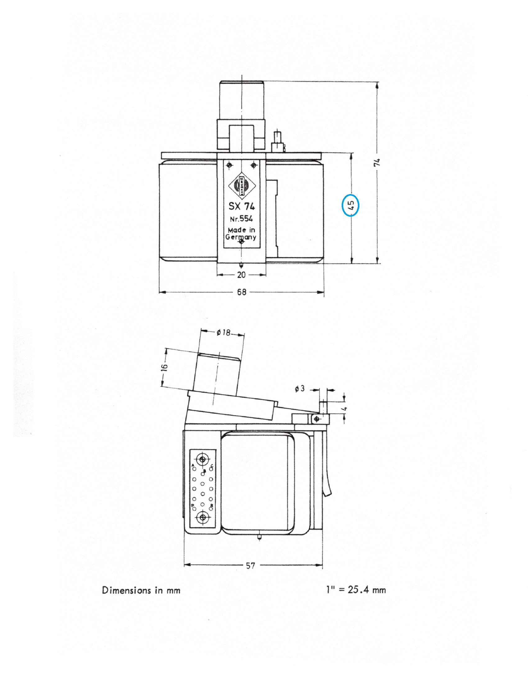
So, the motion of this cutterhead stylus with audio modulation is in a sphere with a radius of ~11mm. Neglecting possible effects of spring-back in the lacquer and whatever else in the cutting process, shouldn’t the effective working length of the cantilever of a cartridge used for playback also be close to 11mm for minimum distortion? Most cartridge cantilevers I’m familiar with are typically shorter than 11mm, many by quite a bit.
More things to keep you awake at night…
Ray K
Have a look at these photos from my files. A Neumann cutterhead stylus is indeed mounted on a cantilever and is actuated by two coils, offset +/- 45 degrees. Here is a photo of a SX-68 that clearly shows the cantilever (with no stylus installed). The cantilever is anchored in a pivot or fulcrum and the stylus end is attached to the L & R coils:
Next up is an undocumented photo that has some dimensions in red (not mine). It could be a SX-68 or maybe a SX-74, which is a newer version of the SX-68. I suspect that the dimension labeled “57 mm” in red is a typo since the Neumann spec sheet shows that dimension to be 45 mm. For the moment let’s neglect the error introduced by the photo having been taken slightly off-angle. The 20mm dimension appears to be about right.
If you scale the cantilever per the corrected dimensions, then the cantilever length works out to be about 11mm:
Here are the actual dimensions of a SX-74 from Neumann’s spec sheet:
So, the motion of this cutterhead stylus with audio modulation is in a sphere with a radius of ~11mm. Neglecting possible effects of spring-back in the lacquer and whatever else in the cutting process, shouldn’t the effective working length of the cantilever of a cartridge used for playback also be close to 11mm for minimum distortion? Most cartridge cantilevers I’m familiar with are typically shorter than 11mm, many by quite a bit.
More things to keep you awake at night…
Ray K
Attachments


Last edited:
- Home
- Source & Line
- Analogue Source
- Thoughts on "tracking tangentially to the groove"