Would a more accurate effective mass come as a result from the calculations below?

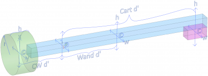
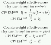
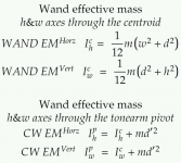
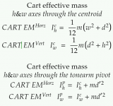
Three mass elements with horizontal and vertical axes on the centroids, with axes on the pivot of the wand.
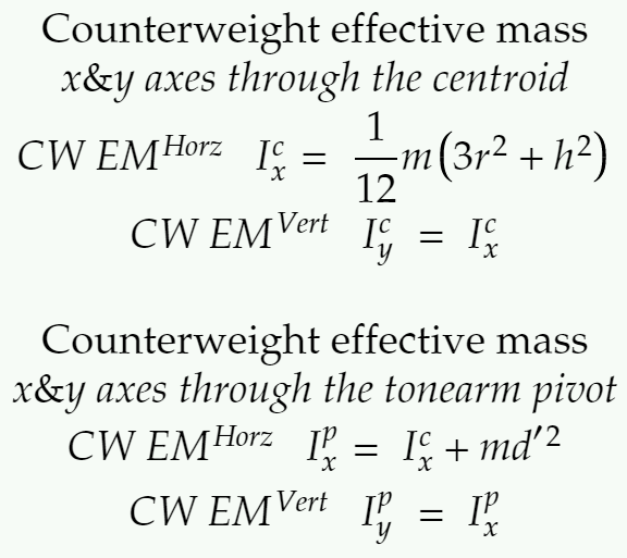
Find I for the CW around the centroid, and sum with the value found with the parallel axis theorem through the pivot.
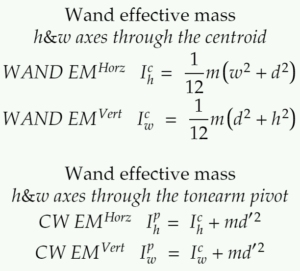
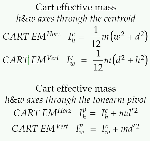
Same for the Wand and Cart, sum the results.
Confirming with a digital twin, and will post that once done.
At first glance, it seems the CW might have a bigger contribution to the overall inertia of the tonearm compared to calculating the CW as a point mass, if I'm seeing this right.
This is still an approximation, and it's possible to model a wand with variable mass distribution, by splitting the wand into multiple mass units to sum.
A possible way to use this for the wand would be to substitute the COM for the centroid, as both have an equal distribution of mass. CW and Cart should be fine, as is.
Both methods for horizontal and vertical are shown, as this could be a stepping stone for me to calculate the horizontal EM for PTTs, what I'm really after.
I'm open to corrections and guidance if I got something wrong.
Three mass elements with horizontal and vertical axes on the centroids, with axes on the pivot of the wand.
Find I for the CW around the centroid, and sum with the value found with the parallel axis theorem through the pivot.
Same for the Wand and Cart, sum the results.
Confirming with a digital twin, and will post that once done.
At first glance, it seems the CW might have a bigger contribution to the overall inertia of the tonearm compared to calculating the CW as a point mass, if I'm seeing this right.
This is still an approximation, and it's possible to model a wand with variable mass distribution, by splitting the wand into multiple mass units to sum.
A possible way to use this for the wand would be to substitute the COM for the centroid, as both have an equal distribution of mass. CW and Cart should be fine, as is.
Both methods for horizontal and vertical are shown, as this could be a stepping stone for me to calculate the horizontal EM for PTTs, what I'm really after.
I'm open to corrections and guidance if I got something wrong.
Attachments
To calculate effective mass "EM" you calculate the moment of inertia"I" for each separate item at its COM. I have a white paper somewhere if I can find it I will post it.
Arm wand I=1/3mr^2 this equation is from the Engineering Handbook and is a good approximation for a uniform beam with the pivot at one end, where r is the COM.
So for a 20cm 10g arm wand with COM in the middle I=10*10^2/3 = 333.333g cm^2
Lets say HS is 9g and COM is 21cm I=9x21^2 = 3969g cm^2
CW stub is 20g and COM is 4cm I=20*4^2/3 = 106.667g cm2
CW is 200g 4cm from pivot I= 200*4^2 = 3200g cm^2
Add all these up = 7609g cm^2
EM = I/r^2 where r^2 = the effective length say 23.9cm
EM = 7609/23.9^2 = 13.3g
This is simplified example and does not include everything like wiring ect. The same method would be used for Horizontal EM. You need to include everything that rotates in the plane.
A Technics SL1200 arm for example has different Horizontal and Vertical EM because it has separate rotating bearing housings for each plane.
Found it.
Just use the equations in my post.
For point mass I = mr^2
For uniform beams, arm wand, CW stub use I = mr^2/3 where r = COM distance from the pivot.
Then to calculate EM of the arm EM = I/r^2 where r^2 is the effective length of the arm and I is the total moment of inertia.
Your first equation m/12(3r^2+h^2)) using radius would only be required if the CW was spinning around its center which it's not.
Attachments
Huygens Steiner theorem yes I'm familiar with it. You are over complicating this.
Did I make a mistake by over complicating it, or is there an actual error?
I'm trying to find a way to calculate the EM of PTTs and this seems a way towards that.
Ok I see.... I missed the PTT sentence in your first post.
I'm not overly familiar with PTT's but I think they have 2 horizontal pivots.
P1 = pivot arm wand is attached to
P2 = main rotational pivot
As P1 rotates it will vary the distance between the CW and HS COM and P2. If this is correct then Horizontal EM will vary across the LP.
I'm not overly familiar with PTT's but I think they have 2 horizontal pivots.
P1 = pivot arm wand is attached to
P2 = main rotational pivot
As P1 rotates it will vary the distance between the CW and HS COM and P2. If this is correct then Horizontal EM will vary across the LP.
At first glance, it seems the CW might have a bigger contribution to the overall inertia of the tonearm compared to calculating the CW as a point mass, if I'm seeing this right.
I'm open to corrections and guidance if I got something wrong.
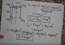
I think I understand where you’re going with this. Let me meander around for a bit and you tell me if I’m on the same page with you. At least in regards to the counterweight what I see is that when people calculate MR^2 they typically treat it as a point mass. A simple MR^2 is ok for a theoretical point mass but in reality the CW has finite dimensions and in terms of MR^2 the rear of the CW contributes more MR^2 to the effective mass of the arm than the front of the CWT. I made a simple sketch to help myself visualize this:
To avoid US/metric conversion confusion I arbitrarily chose a cube counterweight (CW) of 100 mass units, having the dimensions of 40 length units on each side, with the point mass center located at 45 length units from the pivot. By calculating the CW as a single point mass we get MR^2 = 202,500. If I cut that CW in half, glue the two halves together, and calculate the effective mass of each of the two halves individually as a point mass at 35 length units and a point mass at 55 length units, we get total MR^2 = 61,250 + 151,250 = 212,500. If I further split the CW into quarters and calculate the effective mass of each of the quarters individually as point masses at 30, 40, 50, and 60 length units, we get total MR^2 = 22,500 + 40,000 + 62500 + 90,000 = 215,000. All 3 of these CW configurations have the same overall dimensions, have the same center of mass, have the same total of 100 mass units, and will balance the arm and cartridge on the other end the same way.
If we were to subdivide the CW (and the entire arm for that matter) into a near infinite number of small point masses and sum up the calculated MR^2 of each of those point masses, then the sum total should integrate/converge to the true effective MR^2 of the CW. For one iteration of subdividing the CW into halves, the calculated result for effective mass was 4.9% higher than for the single point mass reference. For a second iteration of subdividing the CW into quarters, the calculated result for effective mass was 6.2% higher than for a single point mass reference. I have no idea of how many subdivisions/calculations (integration) need to be done before the answer converges to a number that’s “close enough” to being sufficiently accurate. My background is in electrical engineering and I don’t remember enough of my statics and dynamics 101 class to have a good feel for whether your formulas are hitting the mark. I will agree with you that the CW adds more MR^2 than people are typically assuming when they model the CW as a point mass, and I found similar numbers doodling the math on the other side of the pivot at the cartridge end of the arm.
I looked on YouTube for a primer on the parallel axis theorem but the standard formulas I found to explain it seem to be based on simply modeling everything as point masses
but I get that you are looking for a more accurate solution. Figuring out how to correctly model the effective mass of a PTT looks to be a real nightmare, since how do you determine the actual pivot point(s) that the various masses are rotating about? Wish I could offer more helpful commentary but this is above the level that makes my head spin.
Ray K
Attachments
![EM Calcs [bw].jpg](/community/data/attachments/877/877651-cb619b9191f3972816bc96747ea8c207.jpg)
You are over complicating this.
Our whole hobby is an over complication of what needs to be done to hear music. All we really need is a pair of earbuds and an electronics device with a volume control that goes to “11” instead of just “10”. Right?
These go to 11.mpg - YouTube
Ray K
I looked on YouTube for a primer on the parallel axis theorem but the standard formulas I found to explain it seem to be based on simply modeling everything as point masses
It does not matter that point masses are used to explain the theorem, it is just the sum of the inertia on the centroid/COG and the mass times the distance between the parallel axes squared.
For sure, we are on the same page.
I feel in my gut there is a simplified solution for PTTs, but I'm not seeing it yet, the current method I have is tedious.
At least in regards to the counterweight what I see is that when people calculate MR^2 they typically treat it as a point mass. A simple MR^2 is ok for a theoretical point mass but in reality the CW has finite dimensions and in terms of MR^2 the rear of the CW contributes more MR^2 to the effective mass of the arm than the front of the CWT.
@diyrayk
The increasingly fine subdivisions of the CW volume into thinner discs, are the rudimentary steps of the exact calculus calculation of the MI.
For the CW dimensions and position shown in your example, the exact calculation of % error in MI defined as
[I(point mass) – I(exact)]/[100xI(exact)]
is 6.177%.
The error is insignificant in the larger scheme of things to be concerned about tonearms.
Last edited:
Found it.
Thanks just the paper on tone arm mechanics I was looking for!
@2wise,@warrjon,@diyrayk and et all
Question #1, What are PTTs ?
Questions #2, After reading the URL @ the end of this (ignoring the salespeak)
What is up with the tuning weights ? And will your math help understanding ?
Effective Mass — Basis Audio
thanks in advance,
dennis h
Question #1, What are PTTs ?
Questions #2, After reading the URL @ the end of this (ignoring the salespeak)
What is up with the tuning weights ? And will your math help understanding ?
Effective Mass — Basis Audio
thanks in advance,
dennis h
Hi Dennis,
PTT = Pivoting Tangential Tonearm
I read the blurb and IMO this tonearm is flawed.
1) it uses a low slung CW which will put arm COG below the arm wand potentially causing a pendulum. A tone arm should be neutral in all planes of movement, ie it should move equally in any direction with the same applied force.
2) A uniform tube arm wand fixed into the pivot housing. This has the potential to cause reflections of energy back to the cartridge straight down the uniform tube.
3) It looks from the pictures the stylus is not lined up down the center of the arm tube with the pivot. As the arm lifts this will produce a torque that will also move the arm in the horizontal plane.
Here is some information on a tonearm designed by a Physicist.
Audiomeca Septum & Belladonna - [English]
Here is some information on a tonearm designed by a Physicist.
Audiomeca Septum & Belladonna - [English]
Very interesting read thanks.[FONT=Arial, Helvetica]
[/FONT]
Hi Dennis,
PTT = Pivoting Tangential Tonearm
I read the blurb and IMO this tonearm is flawed.
1) it uses a low slung CW which will put arm COG below the arm wand potentially causing a pendulum. A tone arm should be neutral in all planes of movement, ie it should move equally in any direction with the same applied force.
2) A uniform tube arm wand fixed into the pivot housing. This has the potential to cause reflections of energy back to the cartridge straight down the uniform tube.
3) It looks from the pictures the stylus is not lined up down the center of the arm tube with the pivot. As the arm lifts this will produce a torque that will also move the arm in the horizontal plane.
Here is some information on a tonearm designed by a Physicist.
Audiomeca Septum & Belladonna - [English]
Thank you for the answer and tonearm critique.
Do you think items 1 and 3 are part of the reason why the tuning weights on the Vector Tonearm act differently when placed between the main counter weight and pivot or outboard on the other side of the counter weight.
Have you noticed this phenomenon on other arms ?
tia,
dennis h
- Home
- Source & Line
- Analogue Source
- Effective Mass Method