Where the tuning weighs are placed will effect the the moment of inertia, this will in turn alter effective mass, thus arm cartridge resonant frequency.
The stylus causing a torque around the pivot attempting to rotate Azimuth is well known by the manufacturers. Fidelity Research and others used outrigger bias weights in an attempt to counter this torque. The Vector tuning weights are not going to counter this torque, the weight would have to be offset laterally on the spindle side of the arm like the FR64.
Many arms including the SME IV have the stylus offset from the central plane of the arm. Being a gimbal arm the arm is not going to twist much, but it will still twist within the clearance of the bearings, this twisting also causes the arm to move laterally. Any movement of the arm not following the groove will move the cartridge with respect to the stylus causing the generation of a signal which is distortion.
Ultimately we want only the signal the stylus creates. So in a perfect world the tonearm holds the cartridge rigidly stable and the stylus traces the groove and generates a signal. The opposite is also true, if the stylus is held in the groove and arm is moved a signal will be generated and this signal we do not want.
Our whole hobby is an over complication of what needs to be done to hear music. All we really need is a pair of earbuds and an electronics device with a volume control that goes to “11” instead of just “10”. Right?
Ray K
I made that comment before I realised the goal was to determine lateral EM of a PTT.
The issue is lateral varying I as the arm tracks towards spindle. The best outcome would be to calculate min and max I.
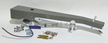
unipivot with secondary bearing
Just to let you know the Basis Vector and the Super-Arm tonearms are unipivot designs. But it has a secondary ball bearing wrap around the up-pointing spike (see pictures below or this video at 1:26 mark) and it requires the armwand housing to "lean" on one side to create a second contact to limit movements to horizontal and vertical so essentially it disqualifies it as a true UNI-pivot tonearm. The leaning force is done by using a counterweight with offset mass, the semi hollowed out area.
I dislike traditional unipivot for having infinite degrees of movement, especially azimuth rocking or instability. But hybrid designs allow creativity in the secondary bearing and the Basis Vector solves the issues of single-point bearing admirably. It retains the unipivot advantages of a loaded bearing, good mechanical grounding, low friction, simplicity but it eliminates azimuth rocking. Yes, the leaning force may generate an unintended horizontal force. The counterweight's hollowed part is on the left side so the potential extra lateral force will be swing to the right side which possibly creates an antiskating force that might actually benefits the design. The Vector belongs in the genre of unipivot with secondary bearing a la Graham Phantom, Continuum Cobra, Simon Yorke S7, SPJ Lyla, etc... If I am in the market for a unipivot arm, I would definitely look for something similar.
PS, what inspired Basis designer AJ Conti to design the Vector arm was his dissatisfaction with the Grapham Phantom. Many Basis turntables were furnished with Graham orignal tonearm but Conti did not like the newly introduced Phantom's use of magnet in "following", the phantom part, the movement of the main bearing housing. He believed magnetic force is compliant and he much prefer a more rigid secondary bearing, hence his invention of the Vector tonearm.
Last edited:
The Vector belongs in the genre of unipivot with secondary bearing a la Graham Phantom, Continuum Cobra, Simon Yorke S7, SPJ Lyla, etc... If I am in the market for a unipivot arm, I would definitely look for something similar.
The secondary bearing concept for a unipivot was done way back in a Gray 102.
Is there by chance a provision for oil bath damping in that Basis Vector cup?
Ray K
Attachments

The secondary bearing concept for a unipivot was done way back in a Gray 102.
Good call, Ray! We can always count on the historically minded connoisseur. I actually owned a Japanese knock off of the Gray at one point but never got to use it before traded away with a friend. I didn't know it has a second contact point.
Is there by chance a provision for oil bath damping in that Basis Vector cup?
Yes, it does as it's shown in this video at the 6:52 mark.
Can confirm from the digital twin the methods in the OP results in exact calculation of the inertial mass, to the fourth decimal at least.
It also shows that even though the point mass method is not exact, the difference is inconsequential.
CW and Wand horizontal and vertical EMs are identical (for this construction), but the cart was dissimilar, from not lying on the centre axis I assume.
This might point to low slung counterweights being affected, not only as a pendulum, but also having dissimilar EMs in the 2 planes. Once more, only as an observation that should have zero or negligible effect.
The answer is none - you can't just divide one point mass into two...or more.I have no idea of how many subdivisions/calculations (integration) need to be done before the answer converges to a number that’s “close enough” to being sufficiently accurate.
To get the exact result with slices, in comparison to the whole counterweight, you must add the mass moment of inertia regarding rotation around the axis through mass-centroid(s) of said bodies:
1) counterweight as a whole body
202.500 + 1/12*100*(3*20^2+40^2) = 225.833,33
2) counterweight sliced into halves
212.500 + 1/12*50*(3*20^2+20^2)*2 = 225.833,33
3) conterweight sliced into quarters
215.000 + 1/12*25*(3*20^2+10^2)*4 = 225.833,33
...and so on with the slicing - no difference. With more elborate shaped bodies the principle is the same, just the calculation becomes not so simple.
my 2 cents for PLT HEM
attachment
Hi friends, once i had posted (on angling for 90°) this hypothesis when trying to calculate the eff mass for my belted Birch TA, hoping for some qualified contribution
I realized that for the horizontal EM two different systems are combined, one of which is variable: something too complex to investigate, for me.
So before looking (rightly) for more precision, maybe it would be better to understand the system to which we intend to apply it -
c
PS in my ignorance I still don't understand why H and V EM should be different: I understand it's damn hard to make them the same, practically impossible on LTA and PLTA, but to do it deliberately...
Attachments
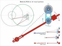
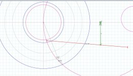
Carlo, the movement of the tonearm is the superposition of two turning motions: once negative (CW) around the center of the Thales circle and once positive (CCW) around the stylus. You have to add the two effective masses calculated from the two movements.
Sorry, I have some difficulty understanding your reasoning, could you detail the calculating procedure or make a graph, please?
On my old graph I see A (a1st type lever?) as a compound pendulum on P2 pivot - which I could therefore calculate with the usual Pivoted TA formulas, if only it could be free to rotate on P2
Then I see B (a 2nd type lever?) as a double pendulum on P1+ P2 pivots, but again the rotation on P1 is not free, but in relation* to the rotation in P1, so I don't know where to start.
The H eff mass derives surely from the combination of the two: you talk about a sum, but I fear it is variable during tracing and far from linear. Not only the B value, but even the A/B ratio.
A PLT is a rigid set, but in which the various masses assume variable distances and mutual angles-
What a mess, at least for me - carlo
Hope this sketch could clarify a bit my previous confused words.
c
Ciao 2wice - even if i'm not up to that math, i know vaguely about Steiner, and was wondering how you could apply it to a PLT.
But looking better at your drawing I see something (... cart?..) very different from usual PLTs and very interesting, can you anticipate something?
c
Ciao 2wice - even if i'm not up to that math, i know vaguely about Steiner, and was wondering how you could apply it to a PLT.
But looking better at your drawing I see something (... cart?..) very different from usual PLTs and very interesting, can you anticipate something?
Attachments
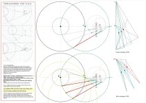
To my understanding:
We can calculate equivalent mass of the moving system referred to the stylus tip meff by dividing the sum total of the inertial moments of the vibrating element around the support point by the square of the distance from the stylus tip to the support point: where I is the moment of inertia and L the distance to the support point.
meff = Σ I ⁄ L²
(taken from here)
Effective Mass = Mass x (COM distance from the pivot)^2 / 3
'Mass' is the mass of the whole tonearm
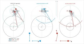
There are two distances: first the radius of the Thales circle
second the distance stylus - COM
Both effective masses are to be calculated and added by signs.
(I did not take into account the mass of the auxiliary arm)
We can calculate equivalent mass of the moving system referred to the stylus tip meff by dividing the sum total of the inertial moments of the vibrating element around the support point by the square of the distance from the stylus tip to the support point: where I is the moment of inertia and L the distance to the support point.
meff = Σ I ⁄ L²
(taken from here)
Effective Mass = Mass x (COM distance from the pivot)^2 / 3
'Mass' is the mass of the whole tonearm
There are two distances: first the radius of the Thales circle
second the distance stylus - COM
Both effective masses are to be calculated and added by signs.
(I did not take into account the mass of the auxiliary arm)
So, if I understand correctly, you suggest to calculate it with the method* we all use (even me) for common pivoted arms-
Unfortunately here I don't see any usual PT around: neither on the - green Pa- radius of the circle nor on the - blue Pb- leg of the Thales triangle; the single COM distances shoud be fixed and the pivot unique and free: conditions absent in a dual pivot Birch.
I only see still the very complex situation that I have tried to highlight in those drawings, Very difficult to calculate for me even empirically, and above all, variable during the arm stroke; just as the relationship between SF and SD that moves it.
Two considerations that weakened greatly my interest for PLTs
thanks for your interest - carlo
* the moments of inertia of the single elements are measured at the COM to Pivot distance, not COM to stylus, using the specific formulas for the different solids (cylinders, tubes etc.).
Attachments
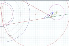
No. As I stated earlier, the movement of the tonearm is the superposition of two turning motions: once negative (CW) around the center of the Thales circle and once positive (CCW) around the STYLUS. I tried to visualize that by showing the movements separately. Since in reality they happen simultaneously, the COG approaches the center of the Thales circle, and the effective mass decreases accordingly as the tonearm moves towards the spindle.* the moments of inertia of the single elements are measured at the COM to Pivot distance, not COM to stylus, using the specific formulas for the different solids (cylinders, tubes etc.).
Attachments

Last edited:
Thank you 2wice for bringing this subject up again since it relates to a current project of mine.
Some years ago, a guy called Hakkaplan on AK suggested an empirical method of effM measurement. He was ignored and left, but I’ve found it to be helpful and fairly accurate. Remove the cartridge and CW and then place the front edge of the HS on a scale. In my experience, the measured weight is remarkably close to the effM. I confirm this by reassembling the arm, mounting a cartridge, running it through the HiFi News resonance tracks and confirming the results on the VE resonance calculator. It worked well enough that I was able to fairly accurately predict the effM change that resulted from switching from aluminum to steel for wand material. It’s not precise, but there’s a phrase in carpentry that fits: “Close enough, nail it.”
I can’t do the math, so I have to put faith in this method and, so far, I believe I’ve been rewarded.
I built a version of Carlo’s Rabbit PLT and measured it using that method. The H effM was higher than the V as expected, but both resonances were within the 7 - 11 Hz range so I figured no harm, no foul. I think the H effM would have been different if the track had been on a different place on the record. I saw similar results measuring a DIY pivoting arm and also noticed the range of resonances like seen in the Korf report Including the higher peaks in the H resonance. That made me wonder if VTF has a damping effect on V resonance(s).
I really don’t think we‘re over-complicating this. It is complicated.
Doug
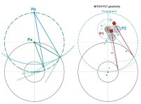
Hi Alighiszem, sorry for the delay but I have tried to understand graphically your model - but unfortunately without any success.
I see just a virtual connection (the radius) of the stylus to the center of the Thales circle, and one - again virtual - (a variable L distance) with the control point of the TA, but couldn't find nothing with a direct, "mechanical" role in that composite movement.
And it still seems to me inexplicable to use the stylus as a reference distance to calculate the moments of inertia of the parts.
Your posts seem to indicate a simple solution to a complex problem. So I think you should explain it in detail, by giving also the relative formulas: many diyers are interested in PLTAs and I believe that, like me, they would be happy to have a feasible and meaningful tool for the design and tests of this type of tonearms.
carlo
Attachments
Hi Carlo,
Thank you for your patience.
The attached video will hopefully help you to understand what I meant.
The red auxiliary arm is moving the blue tonearm around the center of the Thales circle, and the gear moves the tonearm CCW around the stylus.
The result is the movement of any Birch tonearm.
Thank you for your patience.
The attached video will hopefully help you to understand what I meant.
The red auxiliary arm is moving the blue tonearm around the center of the Thales circle, and the gear moves the tonearm CCW around the stylus.
The result is the movement of any Birch tonearm.
I knew a similar geometry, proposed by a French guy if I remember well, and also the Fremer's first Thales commercial tonearm based on similar connections
But what does it have to do with the calculation of the H. Eff, Mass?
c
But what does it have to do with the calculation of the H. Eff, Mass?
c
I can only repeat myself. Our case differs from the case of the traditional tonearms that two pivots and two moments of inertia must be taken into consideration.
Effective Mass = Mass x (COM distance from the pivot)^2 / 3
'Mass' is the mass of the whole tonearm
There are two distances: first the radius of the Thales circle
second the distance stylus - COM
Both effective masses are to be calculated and added by signs.
Effective Mass = Mass x (COM distance from the pivot)^2 / 3
'Mass' is the mass of the whole tonearm
There are two distances: first the radius of the Thales circle
second the distance stylus - COM
Both effective masses are to be calculated and added by signs.
- Home
- Source & Line
- Analogue Source
- Effective Mass Method