Here is a proposal I come up with.
The geometry and dimensions are the same as I provided to Hiten. I attach it here again.

I made a quick model show you the movements.
.gif")
The green parts are magnets. The top one is 2x2x6 mm. The bottom one is 2x2x60 mm. The yellow part is a ceramic ball bearing.

The idea for the slider is borrowed from Schroder LT arm. However, The rail of Schroder LT is a curved magnet that is almost impossible for DIYers to make. Mine is a simple magnet bar. If someone is willing to do it, he may hide the guiding mechanism under the arm base so the arm will have a very clean look.
There is one issue I am not too happy about it. The arm can't stay on the rest position unless you force the top magnet off the rail. Anyway, I believe this arm can sound wonderful as well.
The geometry and dimensions are the same as I provided to Hiten. I attach it here again.
I made a quick model show you the movements.
The green parts are magnets. The top one is 2x2x6 mm. The bottom one is 2x2x60 mm. The yellow part is a ceramic ball bearing.
The idea for the slider is borrowed from Schroder LT arm. However, The rail of Schroder LT is a curved magnet that is almost impossible for DIYers to make. Mine is a simple magnet bar. If someone is willing to do it, he may hide the guiding mechanism under the arm base so the arm will have a very clean look.
There is one issue I am not too happy about it. The arm can't stay on the rest position unless you force the top magnet off the rail. Anyway, I believe this arm can sound wonderful as well.
Now that I have attracted the attention of Ralf, Jim, Doug and others, and there seems to be worthy comments on my sliding pivot approach and variants, I feel it is time to present a definitive basis for the mathematical model it is based on. I hope it is not too rude to quote myself. It saves repetition.
https://en.wikipedia.org/wiki/Limaçon
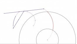
the path of a point fixed to a circle when that circle rolls around the outside of a circle of equal radius. This allows the tonearm path to be determined by a circular guide path.
Although it is not easy to check the claims of the various commercial passive tangential tracking tonearms because the geometrical principles followed are ambiguous to a degree, my firm opinion is that none of them are based on a perfect tangential geometry.
The choice of mid tonearm link has many theoretical and constructional plusses. The link pivot bearing is kept away from the headshell, the overall structure is compact, the guide path does not overlap the playable area.Perfect tangential tracking on the Thales circle requires any point on the tonearm apart from the stylus point, to follow a certain path which is not circular.
The true paths of any point of the tonearm can only be recognised by following it outside of the playable area. This is purely for identification purposes.
The path of any fixed point on the tonearm is a limacon.Once the true path(s) are recognised, there is a well known connection with rolling circles. This is where the circular guide path is discovered.
https://en.wikipedia.org/wiki/Limaçon
the path of a point fixed to a circle when that circle rolls around the outside of a circle of equal radius. This allows the tonearm path to be determined by a circular guide path.
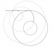
The animations will show the stylus path right up to the disc centre, to emphasise the the geometry is exact at every position. The actual physical components are shown in solid mauve.It is valid for any position on the Thales circle even though only the playable area is of interest.
Although it is not easy to check the claims of the various commercial passive tangential tracking tonearms because the geometrical principles followed are ambiguous to a degree, my firm opinion is that none of them are based on a perfect tangential geometry.
Attachments
The lower part is not necessarily a magnet, it can be iron or steel too. So the Schroeder LT is doable for DIY-ers.The idea for the slider is borrowed from Schroder LT arm. However, The rail of Schroder LT is a curved magnet that is almost impossible for DIYers to make. Mine is a simple magnet bar. If someone is willing to do it, he may hide the guiding mechanism under the arm base so the arm will have a very clean look.
I don't think so. Two magnets can center themselves due to the magnetic field.The lower part is not necessarily a magnet, it can be iron or steel too. So the Schroeder LT is doable for DIY-ers.
Bon,
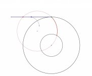
It is no question you have spent a lot of time studying the path of a PT arm. It benefits all of us who are interested in such topics. You have very well summarized the relationships. I have learned as well. In fact, no one disputes that the path of the mid-arm isn't a circle. For practical purposes, the question becomes how we can approximate the path with a circle for the purpose of building a simple and effective tonearm. Please see the image. I added a green circle to your image.
Jim
I agree. It is not necessary to use two magnets to attract. The moving part should be a magnet and the static part, guide rail or "magnet guide", can be magnetic material like iron or steel as suggested by the Schröder patent. While using two magnets is possible but an iron rail is much easier to make than a curved magnet for diy purpose as long as the rest of the tonearm area is made of nonmagnetic material. The narrower the guide the more precise the path it can be.The lower part is not necessarily a magnet, it can be iron or steel too. So the Schroeder LT is doable for DIY-ers.
"Magnet 26, in a preferred embodiment, is constructed of rare earth elements. Magnet guide 19 is made of a magnetic material which can be any ferromagnetic material, like pure iron, nickel and it's alloys, i.e. Permalloy, Cobalt and its alloys or even made from another magnetic material, i.e. rare earth, bariumferrite, AlNiCo. The magnet 26 and/or magnet guide 19 can, among others, be substituted with an electromagnet, likewise is it possible to use, e.g., a permanent or electromagnet that is arc shaped to replace the magnet guide 19."

Yes, you can if you don't care about the accuracy of tracking.I agree. It is not necessary to use two magnets to attract. The moving part should be a magnet and the static part, guide rail or "magnet guide", can be magnetic material like iron or steel as suggested by the Schröder patent. While using two magnets is possible but an iron rail is much easier to make than a curved magnet for diy purpose as long as the rest of the tonearm area is made of nonmagnetic material. The narrower the guide the more precise the path it can be.
Let's assume an arm is 250 mm long and the pivot is at 60 mm from the rear, the magnet is 2 mm in diameter and the non-magnetic rail is 1 mm in width. So, there is a possibility that the magnet is off the rail about +/- 1.5 mm in the rear. Again, let's assume the error is only 1 mm in the rear. The stylus will be about 3.25 mm off its correct position. If you think 3.25 mm is within your allowed tolerance. Yes, you can use a non-magnetic rail.
Last edited:
Bon,
For practical purposes, the question becomes how we can approximate the path with a circle for the purpose of building a simple and effective tonearm. Please see the image. I added a green circle to your image.
Jim
Jim,
I spent months modelling exactly this approach at the beginning of this thread and ultimately abandoned it for a number of reasons including:
1. Approximation and curve fitting with a circle is not as simple as it may appear. Firstly a measure of best approximation has to be agreed. There are many choices that can be made. What is the measure of error? Maximum absolute error, integral least squares error, integral absolute error, etc. Even with 3-point collocation, the chosen points have a bearing on the outcome. The obvious mid, central, inner groove positions will not necessarily minimise whatever error criterion is chosen. It gets even more complicated in translating the approximate circle error into error at the stylus.
2. Once you go the approximate circle route, you throw away loads of geometric insights in favour of number crunching. The precise pivot locations and link that fall out of the exact tangential geometry are simple to describe (and give zero error, what's not to like?). There are other useful data that the tangential geometry places right in you lap. Such as instantaneous centres of rotation that allow perfect description of the skating torque and tonearm horizontal moment of inertia.
3. Circle approximations tracking accuracy are sensitive to tonearm length. In general, there is the same trade-off as with standard pivoting tonearms.
4. It is what nearly everyone else does.
I acknowledge that the real challenge is the engineering required for the rolling pivots.
Bon
"There is nothing so practical as a good theory" Ludwig Boltzmann
"Everything should be as simple as possible, but no simpler" Albert Einstein.
Let's do some experiments.Iron is a magnetic material. Why it is less accurate to create a guide path is beyond me.
1st case. Two magnets. The top magnet always stays in the middle of the bottom rail even you force the top magnet to the sides. The top magnet will move back to the middle of the bottom magnet by itself because both the top and bottom magnets have magnetic fields. The strongest magnetic forces will line up from the top and bottom.
Now let's replace the bottom magnet with a piece of stainless steel. Stainless steel is magnetic material but it is not a magnet and has no magnetic field. You may place the top magnet almost anywhere you want to. The top magnet won't move back to the middle of stainless steel by itself because the stainless steel has no magnetic field.
This is the reason I said the rail must be a magnet, too to ensure accurate tracking.
Last edited:
I am not convinced. You are only making it more complicated. The extra pulling force creates non-linearity and unpredictability and, besides, the magnet is not traveling on a straight line. Also, I don't know if it's possible to find a curved magnet that matches the geometry of the path. A curved iron rod is much easier to implement and by experimenting with magnetic gap width and path width you can tweak it to precision. My hunch is that the Schroeder LT arm uses iron/steel path followed by a moving magnet. Maybe Frank can chime in if he saw this post.
I don't know what is the purpose of self alignment. You have a piece of magnet that attracts a magnetic metal like iron and you shape that metal into a path that simulates the geometry you want and the attraction simply follows the path with no contact, hence frictionless. The magnetic gap determines the strength of attraction and the narrowness of the path determines the tolerance of the tracking. That's it.
Good luck finding a custom made magnet of the perfect shape.
Good luck finding a custom made magnet of the perfect shape.
For the model I proposed above, there is a possibility that the top magnet doesn't align with the bottom rail if the rail is magnetic material such as iron.

If the bottom rail is a magnet, too, the top magnet can align with the bottom rail precisely due to the self-alignment behavior of magnets.
.gif")
If the bottom rail is a magnet, too, the top magnet can align with the bottom rail precisely due to the self-alignment behavior of magnets.
Additional comments about the model I posted above.
I checked the tracking errors of the model and found it has too much of tracking errors. I won't recommend the model. The problem with its underlying geometry is that the Thales circle is too small and the movements are too compressed.
If someone wants to build a PT arm based on this geometry, you need to solve three problems.
1. Build an effective slider.
2. Build an effective guide.
3. Armrest position. The armrest is outside of the path of arm movement. Please see the image.
Last edited:
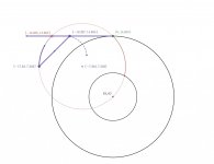
For the geometry I presented, the stylus lies exactly on the Thales circle regardless of the size provided it can reach across the disc. There is no tracking error penalty for using a short tonearm. It is in the maths that governs the geometry.Additional comments about the model I posted above.
I checked the tracking errors of the model and found it has too much of tracking errors. I won't recommend the model. The problem with its underlying geometry is that the Thales circle is too small and the movements are too compressed.
The armrest position will lie on the tangential geometry. This re-inforces my view that the approximate circle geometry throws up problems which are a non-issue for exact tangential geometry. There are still serious constructional solutions required though.3. Armrest position. The armrest is outside of the path of arm movement. Please see the image.
View attachment 1007361
Attachments
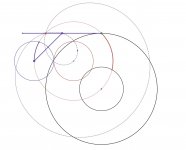
I think it makes no difference. Speaking of Schroder LT, I think I saw somewhere that the rail is a magnet, but I could be wrong since I can't find where I got such an impression. In my opinion, if the rail is just magnetic material, the possibility of tracking errors caused by the rail does exist because the top magnet may move sideways.To avoid confusion, my previous posts were referring to the Schroder LT geometry that uses a magnet to track a CURVED path. Not a fixed point.
Here is a drawing to illustrate my view. The red arrows indicate small side movements.
Bon,
I have no doubt that if you follow the geometry as you outlined here, please see the image, there will be no tracking errors. But it is at the cost of complicated construction. In the model I proposed in #241, I was trying to simplify the construction. However, it introduces too much tracking error to accept it as a valid proposal. Approximating the curve with a circle accurately requires a large Thales circle and expended movements.
Jim
- Home
- Source & Line
- Analogue Source
- A tangential tracking pivoting tonearm