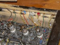
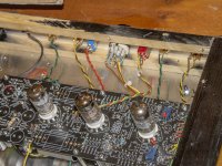
That's why I posted the links. Because the PCC tubes are designed to work in series in TVs there is no need for them to have a fixed voltage, they need to be run on a fixed current of 300ma. The idea being that all the valve heater voltages would add up near to the local AC supply voltage, and hence not need a heater winding on the power transformer. The voltage is irrelevant.
That said, just out of curiosity I've just measured current on V1 & V3 on my BB, and it appears to be only just over 100ma, but it certainly doesn't seem to affect the working of the unit.
I say that, but not having heard it with the specified 300ma feeding these valves, I don't really know, but I would have imagined that like a "normal" voltage driven valve, higher power would result in better performance (up to a point of course)
Which leads me to a question, would it be beneficial to increase the current through V1 & V3 to 300ma, and how would this be achieved?
Maybe Alan or Oli could comment
Organ Grinder here.
What I think you are probably doing is using a multimeter that has an internal resistance on the selected range used, that is limiting the current passing through the valve. Usually small valve heaters will glow a dull red/orange when at the correct temperature, when measuring the current is the look of the heater the same as when operating normally?
You are correct in saying that P series valves were designed to operate at a certain current level (0.3A) but the specification for the heaters usually gives +/- 5% range.
The level of emission from a heater at correct temperature is way in excess of the emission actually needed to function correctly, plus the valves in the BB3 are not run at full ratings.
It is also fairly common for PCC88's to be used where ECC88's would be better suited to the heater voltage, particularly in some Tim de Paravacini designs.
That is -10% below and the amplifier still works.
There is no concern of how the valve heaters are powered.
I'm using an autoranging mm.
But the P valves do appear to be operating correctly, with the normal orange glow.
I was just curiosity more than anything.
ZD2P is for gate protection of the Mosfet filter.
What is your high voltage AC input, around 170 to 175 is ideal. Sounds like you have a lot more.
The HT can be reduced some by fitting a resistor across C5P, try fitting a 1 Megohm and see what you get.
Here are my data:
AC out from trafo 260v AC
C4 342v
C4 323v
C7 323v
C8 284v
Is This so high that I ought to change trafo??
Looks ok from here [emoji4]Not shure If that picture was right..
Still very happy, but wondering if I could be even happier. There's just a touch of harshness in the mellow of my top end. Everything else, I really love and don't want to change, so it really is just that little tweak...
So I'm wondering where to start. I've not yet made the 68-->73k RIAA resistor mod, but it seemed to me that's minor and probably not going to be audible to my 60 year old ears anyway.
I think I've got three choices:
Suggestions appreciated.
So I'm wondering where to start. I've not yet made the 68-->73k RIAA resistor mod, but it seemed to me that's minor and probably not going to be audible to my 60 year old ears anyway.
I think I've got three choices:
- Input capacitance.
- One or more valves. Currently ECC83 Harma Retro, and PCC88 - 7DJ8 National Matsushita
- Output capacitor. Clarity CMR with close to 100 hours on them
Suggestions appreciated.
Use the resistor mod as that directly affects the HF response and removes a little overshoot on the square wave.Still very happy, but wondering if I could be even happier. There's just a touch of harshness in the mellow of my top end. Everything else, I really love and don't want to change, so it really is just that little tweak...
So I'm wondering where to start. I've not yet made the 68-->73k RIAA resistor mod, but it seemed to me that's minor and probably not going to be audible to my 60 year old ears anyway.
I think I've got three choices:
- Input capacitance.
- One or more valves. Currently ECC83 Harma Retro, and PCC88 - 7DJ8 National Matsushita
- Output capacitor. Clarity CMR with close to 100 hours on them
I was going to order some of those Russian PIO capacitors discussed earlier, but just wondered if that was where to start or finish...
Suggestions appreciated.
71k or as close to it is pretty much perfect.
Get some decent valves in it too.
Caps.....I'll send you a matched pair of the Russians for cost. No problem. Just drop me a message
I use a DC PSU and put around 140vdc through them for a week, left on 24/7Quick one for Oli.
What do you use to burn in your coupling caps, what amount of power and how long?
Many thanks.
Nothing fancy, but it does seem to help get them over the first few days of inconsistent sound quality
Take not of which side is + and - once connected to the PSU.
When you fit them to the BB3, Fit the - side of the cap to the terminal nearest the output on the BB3
Last edited:
Ooooh, that's cool....I'll be building one!
Here are my data:
AC out from trafo 260v AC
C4 342v
C4 323v
C7 323v
C8 284v
Is This so high that I ought to change trafo??
I have mounted the new trafo and now I have 238v at C4P and 220v at C5P.
A little lower than it was before....
- Home
- Source & Line
- Analogue Source
- Bigbottle Phonostage Builders thread.

