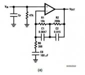
That circuit already has the standard 40db of gain at around 1kHz rising to 60db at 20Hz.
Make that 35db and 55db. Dropping the 390 to around 190 ohm will bring the 1k gain up to 40db
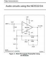
The 5532 can drive much lower impedances than a LM35x jfet opamp could.
How well this is worked out is questionable, 50 Ohms is pushing it for the 5532 and with 47uF the bass will be sagging below 100Hz. There will be high levels of 1/f noise due to that capacitor impedance rising at low frequencies.
How well this is worked out is questionable, 50 Ohms is pushing it for the 5532 and with 47uF the bass will be sagging below 100Hz. There will be high levels of 1/f noise due to that capacitor impedance rising at low frequencies.
The circuit is from LM833 bipolar opamp app. note. Anyway, I've seen often that Japanese companies use very low values in the feedback circuit. One example is my Yamaha AX592 amplifier that uses 510R feedback and 220R gain setting resistor. OPamp in Yamaha is NJM2068 but I use NJM2114 which is champion among high performance opamps having 60mA output current! Only NJM4556A has more output current but it is special opamp for headphones. 190R gain setting resistor will work in the circuit from post 1 with NJM2114, but what will be the penalty in distortion I don't know.
I doubt distortion would figure much in the scheme of things for the simple reason that levels are way below clipping for normal operation. That means the opamp is not working hard driving the feedback loop.
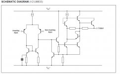
The LM833 is a actually very good opamp but there are two versions surprisingly.
The current Texas Instruments LM833 uses an NPN quasi complementary output stage to overcome the problems of fabricating high speed 'high power' PNP devices onto the chip and offers better performance the original versions that used a classic NPN/PNP stage.
Texas also offer an LM833-N which does still use the PNP output stage. Also have a look at post #78
About op-amps use.
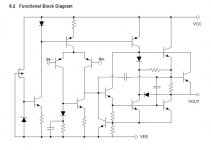
In fact I am perplexed, it's strange looking schematic.
That will just be an outline rather than a fully drawn schematic. This is the TI version, again its not complete.
Attachments
The differences between makes , like these output stage differences, can make the circuit work with one and not the other. It's odd that the pnp was dropped as making a decent pnp is much easier these days with ion implantation. I remember back 40 years ago when only Harris had a vertical pnp transistor.
- Status
- This old topic is closed. If you want to reopen this topic, contact a moderator using the "Report Post" button.
- Home
- Source & Line
- Analogue Source
- RIAA circuit help needed