These values give 40dB gain at 1kHz and are very close to the RIAA curve:
R1=33k
R2=390k
R3=390R
C1=2n2
C2=9n4 (2x4n7 in parallel)
C3=100uF
The original design is not accurate, with a "warm" balance
I finally built the circuit with your recalculated values and must say that I like it much better than the original LM833 app note circuit. Compared to your circuit values, the original circuit sounds too dark and smeared for my taste. Your circuit is brighter and more detailed so I decided to amend my Eagle PCB and schematic files for the values from your simulation with two 4n7 cap footprints in parallel. Do you have RIAA deviation result for your simulated circuit?
Philips actually have a worked example in their AN142 '5532/5534' applications data sheet that sees the feedback return reduced to 49.9 ohms. This looks to be designed for absolute minimum low noise.
The 47 uF decoupling the 49.9 to ground definitely is too low. I’d use a 1000uF there fo4 reasons touched on by an earlier poster.
50 ohm is so far below the equivalent noise resistance for an NE5534A its silly. 3.5nV/√Hz is about that of a 750 ohm resistor. A 150 ohm resistor has 1.6nV or so, upping 3.5nV to 3.85nV, which is a pretty negligible increase, no need for any smaller resistor value than that, and every reason (avoiding excessive capacitor sizes) to not go lower. In practice other sources of noise will be dominating anyway, so 220 ohms for the lower feedback network leg is a common choice.
Perhaps they were trying to cover MC and MM in one compromised design? Not a good idea.
Perhaps they were trying to cover MC and MM in one compromised design? Not a good idea.
Last edited:
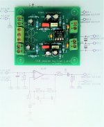
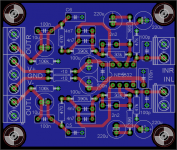
Here is the photo of my original PCB which is good for every active RIAA EQ that uses topology from LM833 app note which is the same as Bonsai's Hifisonix RIAA EQ amplifier. I did not use footprint for parallel cap in EQ section of the circuit so I had to solder it on the bottom side. I shall try Bonsai's circuit values in the next few days and report my impressions. The only thing that my PCB does not have is secondary post filter (like in the Bonsai's circuit and like one used in very good budget phono amp NAD PP1) I use two series electrolitics to ground with negative sides connected with the gain setting resistor. It's much cheaper than bipolar elco. I use great NJM2114 opamp for all my builds. It's a kind of improved NE5532.
Attachments
Last edited:
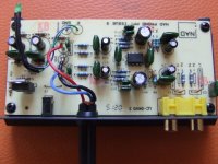
I intend to make new PCB that will include secondary post filter. There is enough space on the PCB for it. I shall keep input cap to ground so that I can fine tune input loading for any cartridge on the market. (100pF is good allround compromise).Take a look at the NAD PP1 schematic. It has all the goodies for a simple RIAA circuit.
Attachments
That device seems to be end-of-life alas. Its basically like two fully compensated NE5534A's in one device (the NE5532 opamps have slightly worse performance than the NE5534A).I use great NJM2114 opamp for all my builds. It's a kind of improved NE5532.
That device seems to be end-of-life alas. Its basically like two fully compensated NE5534A's in one device (the NE5532 opamps have slightly worse performance than the NE5534A).
I bought hundred pieces few years ago. Enough for my life.
Here is the deviation from the ideal RIAA curve for a preamp with the values from post #3:
RIAA circuit help needed
I calculated it by connecting an accurate inverse RIAA filter at the output of an RIAA preamp with the above mentioned values.
The deviations are rather large, IMHO.
Regrads,
Braca
RIAA circuit help needed
I calculated it by connecting an accurate inverse RIAA filter at the output of an RIAA preamp with the above mentioned values.
The deviations are rather large, IMHO.
Regrads,
Braca
Attachments
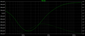
Sorry, my typo, it should've read post #7, since you wrote to have built a preamp with the values suggested by @davidsrsb.
Thus, the simulation is valid for the values from post #7.
Main reason for the deviation is the capacitor C2. Using the spreadsheet from Bonsai:
RIAA Equalizer Amplifier Design
its value should be 8.16nF for a perfect RIAA curve with other component values unchanged.
Regards,
Braca
Thus, the simulation is valid for the values from post #7.
Main reason for the deviation is the capacitor C2. Using the spreadsheet from Bonsai:
RIAA Equalizer Amplifier Design
its value should be 8.16nF for a perfect RIAA curve with other component values unchanged.
Regards,
Braca
With circuit from post #1 and values from @davidsrsb sim, and C2 reduced from 9n4 to 8nF, sound is even better! With these values I do not feel the need to use tone control preamplifier. Most recordings sound clear and bright, but not overly bright. It is now obvious to me that accurate RIAA EQ is beneficial from the subjective point of view. The most important conclusion is that great LP reproduction is possible with simple RIAA circuit. The only necessity for the PCB design is that we need one more component footprint for C2 position. In fact, if precise EQ is needed it would be beneficial to use three footprints in that position because I still need some 150pF to get it right.
I used these LPs for quick evaluation of sound quality with C2 = 8nF, some of which I would not call "decent recording quality", let alone "great recording quality". I use some of it just because of the bad recording quality.:
1. Pat Metheny Group "Still Life (Talking)". This is digitally recorded LP that tends to sound hollow if RIAA EQ is not proper. There is a lot of instruments that are struggling to be heard, it's a mess of sounds that somehow always leaves the impression of hollowness. It competes with Al Jarreau's 80's recordings for the title of the worst recorded great music. Still with this RIAA circuit the sound was nearing the category of "decent".
2. Oscar Peterson "The Trio". This is live in studio recording, very thin, very confused microphone positioning, obviously made as some kind of routine. No attempt was made to get it right. It was just like you gave mixing desk and microphones to somebody that is not interested. Still, great music that managed to find it's way to the heart of the listener in spite of bad recording. With too bright RIAA EQ piano can sound more like xilophone. With low frequencies dominating you just can't comprehend Oscar's, Niels's and Joe's virtuosity.
3. Joe Diorio & Robben Ford "Minor Elegance". This is in fact great sound recording. German producers and German record company. This is how all records should be! Full frequency spectrum and all of it near saturation. But if your RIAA EQ is not right hi-hat can sound aggressive and distract attention from the important aspects of music. A little warmer presentation than necessary and the whole music just looses it's meaning. Again, this RIAA managed to pass to the category of "decent".
Last edited:
My PCB would not need any rework if 8n2 cap would be available. In that case only one footprint will be enough. But I can't find 8n2 poly caps with 5mm lead spacing in local shops. Only 6n8 and 10n, nothing in between.
I shall change footprints for series back-to-back elcos to earth, so that two 1000uF/16V caps can be used to get 500uF.
I shall change footprints for series back-to-back elcos to earth, so that two 1000uF/16V caps can be used to get 500uF.
You don't have to search for capacitors with exact values - just provide two footprints per capacitor position on the PCB and then combine by paralleling.
For example, 8n2 is a combination of 4n7 and 3n3 capacitors, and a 220 pF C0G capacitor can always be strapped across one of them at the back side of the PCB to make up for the missing 200 pF.
This method is cheaper and more flexible than searching for a single capacitor with the exact value.
Regards,
Braca
My PCB would not need any rework if 8n2 cap would be available. In that case only one footprint will be enough. But I can't find 8n2 poly caps with 5mm lead spacing in local shops. Only 6n8 and 10n, nothing in between.
I shall change footprints for series back-to-back elcos to earth, so that two 1000uF/16V caps can be used to get 500uF.
Its best to design for just E6 or E3 values for capacitors if possible as these are commonly available. By series and parallel arrangements you not only can have many different values from these basic values, but you gain a modest increase in accuracy since the combined value is less sensitive to variation than a single capacitor. Using four 2% caps you get 1% tolerance, for instance, assuming the usual bell-curve distribution.
E12 values that aren't E6 (1.2, 1.8, 2.7, 3.9, 5.6, 8.2) are much harder to source for capacitors (especially as you want high tolerance caps), whereas resistors are easily sourced in E24, E48 and E96 values, at 1% or better.
In one RIAA design I split the poles and zeroes of the response apart into separate sections so I could use 10nF capacitors throughout - this is a bit profligate in circuitry, but works and is much easier to design as each time-constant directly maps to an RC pair.
Last edited:
50 ohm is so far below the equivalent noise resistance for an NE5534A its silly. 3.5nV/√Hz is about that of a 750 ohm resistor. A 150 ohm resistor has 1.6nV or so, upping 3.5nV to 3.85nV, which is a pretty negligible increase, no need for any smaller resistor value than that, and every reason (avoiding excessive capacitor sizes) to not go lower. In practice other sources of noise will be dominating anyway, so 220 ohms for the lower feedback network leg is a common choice.
Perhaps they were trying to cover MC and MM in one compromised design? Not a good idea.
I agree 50 Ohms for the gain setting resistor is a waste - I usually use 150 or 2 x 150 in parallel - you can shitft the gain by 6 dB in most all active RIAA with minimal real effect on the overall conformance.
But, if you are going to use 50 Ohms, then use a decent size DC blocking cap. The simple RIAA on my website uses 470uF Bip devices.
The NE5534 is a great opamp for MM RIAA - I think I paid about 40c each in a tube for performance that cannot be convincingly beaten without spending 10x o2 20x that. Douglas Self is absolutely correct when he says its the best device for MM.
- Status
- This old topic is closed. If you want to reopen this topic, contact a moderator using the "Report Post" button.
- Home
- Source & Line
- Analogue Source
- RIAA circuit help needed