In the case of the series regulator here, the high THD seems to be a manifestation of some other problem. I suspect that when that's fixed, it might be the best of this bunch.The smoking gun in that case was actually looking at the sine excitation waveform and seeing stuff that absolutely shouldn't be there.
I've been playing little tricks to increase the loop gain of the suspects presented here. In some cases, the benefits are straightforward, in others, the regulator becomes somewhat difficult to compensate to get an optimally damped response (I insist on that). More results when I'm satisfied.
If you have a yen to be useful here, one of the things you could possibly do is check out the results of the regulator shootout in Linear Audio and mention them here in passing. What would be really useful would be a mention of the regulator topologies compared. Were they all series-pass, or were series-pass compared with shunt regulators? I'll get around to buying all the Linear Audio releases so far - a worthwhile activity for anybody trying to gin up their own audio circuits - but, It'd be nice to see how some of the competition is performing.
The usual series pass regulator can source current but not sink it - a properly done shunt can do both. Think about that...
The regulators in the article were Linear Tech LT1963A/LT3015;Pooge 5.51, Sulzer, LM317/LM337; Enhanced Jung/Didden (2000), Invisus (discontinued now), PA's Sjostrom, SALAS Bib (shunt), Bybee "Music Rail", Belleson, Burson, Super Teddy and New Class-D.
The Bybee isn't a regulator per se, but had so much hype it had to be included.
If you want to retest, I would suggest building the unmodified 1995 Jung regulator (and Walt has the articles archived on his website) and comparing designs to this. I found that the noise and PSRR tests I ran compared quite well to what he published, he did better on the Z-out test, but then again he's older than me!
I've been poking around with the "Amplified Zener" shunt reulator (the second shunt I presented here), and found that a couple of small tweaks greatly improved the output impedance and THD.
Please note the attached schematic. I added a voltage drop in series with mosfet M1. Ideally, this should be a voltage drop with as low an impedance as possible, so as not to add too much degeneration to M1. In this schematic I used a 2V voltage source and 15 ohms in series to approximate a GaP yellow-green LED. I've found that a small mosfet like the 2N7000 or BS170, etc. with gate connected to drain works pretty well, too.
Adding the extra drop in series with the source of M! allows me to increase the value of Resistor R4, increasing the loop gain of the regulator. To get the desired 30V output, I used two 15V, 1W zeners in series, as for some reason, Orcad/PSpice doesn't have the model for the 30V device.
The last thing I did was to increase the bias current in the current source feeding the regulator by reducing the Value of R1 from 4R7 to 3R3. This increased the bias current from ~150 mA to a little over 200mA.
The next posts will show a tidy improvement in output characteristics as a result of these changes.
Attachments
This first slide show the response of a current step from 50mA to 100mA, 50usec wide, with 100 nsec edges and 100usec rep rate. This is quite a rigorous test, a much more severe load than any audio preamp would represent in normal operation.
The output transient response at the leading and trailing edges is dominated by the ESR of the output capacitor (190 uF, 0.005 ohms, equivalent to 4 X Nichicon 47uF, 50V polymer caps in parallel).
The transient settles down to a DC response to the load step indicating an output impedance of 0.6 milliohms.This will be hard to realize in an actual circuit simply because the amp/regulator has to be a finite size, and the traces hooking the parts together don't exactly have zero resistance
Attachments
Finally, here's the response to a 20mA, 10kHz sine current source superimposed on a 100mA static load. This is a much more severe load than would be represented in practice by a normal preamp circuit (what would your preamp be doing to draw 20mA at 10kHz?). The voltage excursion induced by the sine current is small, and the THD has been improved by the changes.
Attachments
Last edited:
It appears that the family of shunt regulators shown here (and I expect others as well) benefit greatly from extra loop gain, and more importantly, increased bias current.
This is in line with some observations made in passing by Salas in his "Simplistic RIAA" regarding improved lisenability with increased bias current in his shunt regulator. I'm not going to even try extracting that information from that sprawling pile of a thread - if someone else feels eagar enough to dig for it, they can have at it. Maybe Salas will happen by and help out - it's been known to happen... At any rate, the improved THD with higher bias current may point to a reson for the improved listenability.
Attached is a schematic for an improved version of shunt regulator #3 presented here previously. Adding extra voltage drop (in the guise of a 2N7000 with drain connected to source) in the pmos gain element allowed me to increase the load resistor in the previous stage, increasing the loop gain of the regulator. Increasing the bias current (2.7 ohms vs. 4.7 ohms for the current-setting resistor in the ring-of-two current source feeding the shunt) also improved things quite a bit.
Attachments
Here is the actual 10kHz sine response and THD. Keep in mind that this is for a 20mA sine excursion on top of a 100mA load - a far more severe test than one would encounter in normal operation. The sine is clean, and the THS is low. There should be correspondingly lower THD with a smaller current excursion, but it's hard to demonstrate in simulatiion, as the results get grainy with smaller excursions.
Attachments
I've been through three variations of a discrete series-pass regulator in the background of this thread, and all three have the same defect that jackinnj first pointed out - they have low level high frequency hash on the output that messes up the low level THD, which may impact their sonic signature/listenability.
All the shunt regulators I've messed with here so far can be fixed by increasing the current delivered to the shunt portion of the regulator by the input current source feed, as well as with some minor tweaks that address the regulator loop gain. Nothing seems to fix the series pass regulators so far.
I'm going to try a couple of simulations for opamp-based series regulators similar to the Jung/Sulzer, etc. types to see if including a ton and a half of open loop gain fixes this problem (though the concept is somewhat repugnant). More later.
Just for grins, I ginned up a simulation using a OPA541 power opamp as a series-pass regulator that can both source and sink current. It needed relatively few parts to get going, and its response to a 10kHz sine current load was clean. It may be that the key to cleanliness is the ability to source and sink current. I'll find out when I compare that solution to a conventional opamp-based regulartor that can only source current.
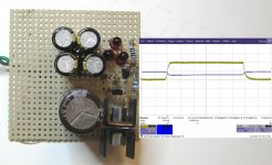
Last night, I built up a grubby perf-board prototype of the series-pass regulator shown in post #17 of this thread, though without C4/R14 and C3/R13. I also used an IRF9610 rather than an IRF9520 for M2.
The supply regulated nicely at around 30.2 VDC for a 40 VDC input. At work today, I loaded it with one of our Kikusui electronic loads and gave it a dynamic load step, while monitoring the output voltage with an AC coupled 1X probe. The output response to the load step is very well-behaved. You can't see the output noise of the power supply over the self noise of the digital scope (the trace with power supply is no thicker than the thickness with no supply connected). The supply shows a ~0.8mV excursion for a 100ma load step, which works out to 8 milliohm output impedance. If I changed my monitoring point to near where the output voltage is actually sensed by the regulator, I may be able to better that.
The supply regulated nicely at around 30.2 VDC for a 40 VDC input. At work today, I loaded it with one of our Kikusui electronic loads and gave it a dynamic load step, while monitoring the output voltage with an AC coupled 1X probe. The output response to the load step is very well-behaved. You can't see the output noise of the power supply over the self noise of the digital scope (the trace with power supply is no thicker than the thickness with no supply connected). The supply shows a ~0.8mV excursion for a 100ma load step, which works out to 8 milliohm output impedance. If I changed my monitoring point to near where the output voltage is actually sensed by the regulator, I may be able to better that.
Attachments
Last edited:
For grins, here is a regulator based on an OPA541 power opamp. I'd expect similar behavior out of an OPA549. This is quite possibly the only way I'd let one of these things near my audio gear... At any rate, the parts count is not too extreme, and it behaves itself, though more tweaking of the output capacitance may be in order. The error associated with the current sense node doesn't appear to be affecting the operation.
Attachments
THe output impedance of the regulator as presented is nothing particularly shecial (~4.5 milliohms). The response to a sine wave current source load (20 mA with 0.1A DC bias) is pretty pure, no doubt helped along by the fact that the opamp is running Class A, and the fact that there's all that open loop gain to be had...
Attachments
Attached is a repeat of measurements of the regulator shown in post #52. As before, the regulator was tested using a Kikusui electronic load, with a load step of 50mA - 150mA - 50ma. This time the voltage sensing point was shited to directly across the voltage divider network for the error amp to get a better sense of the native output impedance of the regulaotr without intervening voltage drops.
As can be seen, the changed sense position greatly reduces the voltage shift for the same magnitude of current step. The output voltage excursion is 0.2-0.3 mV for a 100mA load step - this calculates out as 2 to 3 milliohms output impedance. Of course you'll only see that lower output impedance if your load is hooked up right at the sense point. Anything farther away will also have the intervening impedance of the connecting traces/wires added to the intrinsic output impedance of the regulator.
The moral of the story is that you put your nastiest load (like a line amp) closest to the regulator sense point, and the less difficult loads farther away.
Attachments
- Status
- This old topic is closed. If you want to reopen this topic, contact a moderator using the "Report Post" button.
- Home
- Source & Line
- Analogue Source
- Low Noise Discrete Power Supplies for Phono/Line Preamps