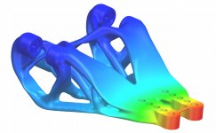
During simulations to measure the truths to a rigid grounding topology for tonearms being superior, I modelled a theoretical carriage with the optimum weight/stiffness, max deflection @ 10 time working load is about 0.5um. Vanishingly small.
Carriage weight ~9g.
I'm not building this as my interest lie elsewhere, just an experiment.
Very interesting concept, what material did you model it in. I have been looking at how I build a lighter carriage but keep the stiffness of the current one.
Very interesting concept, what material did you model it in. I have been looking at how I build a lighter carriage but keep the stiffness of the current one.
The only material in the sim library that the service has is PA6, so I used that.
Another 2 post processing methods could see the stiffness increased by a magnitude or two for each process.
Displacement = 5.5E-03mm @ 100g load. 100g is excessive but I could not get the topology optimization to run with an aesthetic looking solution at a lower load.
Attachments
During simulations to measure the truths to a rigid grounding topology for tonearms being superior, I modelled a theoretical carriage with the optimum weight/stiffness, max deflection @ 10 time working load is about 0.5um. Vanishingly small.
Carriage weight ~9g.
I'm not building this as my interest lie elsewhere, just an experiment.
Very cool! It looks like it comes out of the lord of the ring.
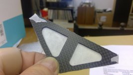
Expertise needed please, not really on topic, sorry about that! i thought the parts were coming along nicely and then i started drilling holes, big ones so i could make the cut outs in this part attached were fine, but small holes wander when you hit the fibres instead of resin (i guess) so i have wrecked two head shell plates so far and when i start drilling this part for the bearings the same will likely happen.........this will not be pleasing as it was a lot of work to get to here!
I don't have a pillar drill, was hoping to complete the budget arm with hand tools, any ideas please gents?
I don't have a pillar drill, was hoping to complete the budget arm with hand tools, any ideas please gents?
Attachments
I don't have a pillar drill
Sorry, I was going to suggest a pillar drill!
Try drilling a piece of alu sheet at the size of hole you want, then clamping / taping it securely to your workpiece. Use the harder material as a guide.
Oh, and be careful with the CF dust when you're filing. You don't want to be breathing much of it in.
Mike56;6268401 I don't have a pillar drill said:Since you are not a expereinced machinist, look up you tube videos on jig building for ideas on how to do it with hand tools. It can be done, but I have access to most of the cool tools of a machine shop so I haven’t acquired the knowledge to do any hand holding with jigs, sorry.
Dennis h
Dennis is right,
Make a jig out of either aluminium or steel that has the holes you need drilled in it. These do not need to be the final size as once you have a pilot hole in the CF any other drill follow the pilot hole.
Clamp the jig to the CF, the jig will prevent the drill from wandering.
I often use blue permanent marker as a layout die when marking out parts. Use a scribe and if you have digital calipers they can also be used to scribe lines parallel to edges.
.
Last edited:
It really does depend on the accuracy needed but I often find that using a dremel with a fine diamond pointed stone does a better job than a twist drill.
Something like this
30pcs Diamond Rotary Dremel Burr Drill Engraving Bits Set For Stone Tiles Glass | eBay
Something like this
30pcs Diamond Rotary Dremel Burr Drill Engraving Bits Set For Stone Tiles Glass | eBay
drilling
Hi Mike, all the indicated methods - blue marking - pilot hole + progressively larger tips, or the use of jigs are excellent. but insufficient to make a true parallelogram, and the smaller the parallogram the greater the required precision.
Geometrically a parallelogram is a polygon with opposite sides strictly parallel.
So to make one simply - as clearly indicated in the construction drawings of the LC, just take those parallel sides together, and drill them in pairs.(vertically, of course)
If the parallelogram comes out a bit larger or smaller, it doesn't absolutely matter, it must instead be just strictly parallel, otherwise it will go off-axis and/or brake.
Meanwhile congratulations for how you're working the CF; but I would have made the levers in one piece directly from plate, not glueing 3 different, introducing a lot of possible misalignments
carlo
in the LC the only important innovation in LTA design is the radial rail, the parallelogram is just the price to pay to get it.
RE: drilling
"So to make one simply - as clearly indicated in the construction drawings of the LC, just take those parallel sides together, and drill them in pairs.(vertically, of course)
If the parallelogram comes out a bit larger or smaller, it doesn't absolutely matter, it must instead be just strictly parallel, otherwise it will go off-axis and/or brake."
Excellent, one who understands the whys and wheres of a part will be the most succesful in making it. (what is important and why,and what is not important and why)
dennis h
I agree 100% now Carlo, how difficult could i make it all!?!just take those parallel sides together, and drill them in pairs.(vertically, of course)
If the parallelogram comes out a bit larger or smaller, it doesn't absolutely matter, it must instead be just strictly parallel, otherwise it will go off-axis and/or brake.
Meanwhile congratulations for how you're working the CF; but I would have made the levers in one piece directly from plate, not glueing 3 different, introducing a lot of possible misalignments
carlo
.
Next time it will be different, for now i hope to complete this route, even if to be .....y minded! - and many thanks for your input and thoughts!
Excellent, one who understands the whys and wheres of a part will be the most succesful in making it. (what is important and why,and what is not important and why)
dennis h
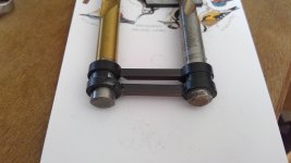
I have adopted the principles, so the verticals will be "co-drilled, the horizontals glued on a jig - i have also learnt that pultruded carbon tube splits when you push the bearing in..........so i have doubled the tube now, if i knew all this before i started a drilled plate is so much easier and with the amount of material involved aluminium, which drills straight, is hardly any heavier! if i can i will get this hard work variant sufficiently complete to play some music soon and see whether i feel a rework worthwhile! best, mike
My admiration for those of you who have built a working LTA grows continually and for those who have built lots, developed and refined them, even more.
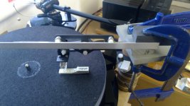
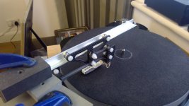
I know i made some poor decisions, however i am going to complete what has now to be called MK 1 and I couldn't resist sending a couple of pics as i have temporarily mounted it on the TT now, if that G cramp and a pile of hole cutter offcuts can be called a mount, just to see if i have got most things in the right place. Well i built a mirror image of the rails by mistake, so that's point 1 but otherwise it looks to me to achieve getting the stylus under the radial rail with the parallelogram on the carriage.
I will refine some adjustable weights on levers using nuts and bolts to replace the blue tack and aluminium experiment and keep on going!
Attachments
1, 2, 3.
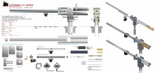
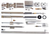
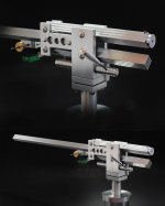
Lil Casey prism almost ended, and at first sight seems to behave properly.
Sooner or later will follow my infamous "crash test", and as usual, the vertical and horizontal friction measurement, good or bad it would be. From what can be seen from these first laps, I expect (well, i hope) to find rather similar values to that of Mk2 carbon, despite an higher weight. Maybe this new one is built with more precision.
The double vee carriage - the only curiosity that brought me to build this version - runs smoothly (....after a very tedious lapping job) and, as previewed, it has no tilting, even trying to rotate it by hand.
But this topic (pivot stiffness) perhaps deserves a little more in-depth discussion, because once again common sense does not help.
carlo
Go on, Mike & Co, you are starting where i'm ending, and there is a lot to learn. But active... or passive??
Attachments
Last edited:
Very nice work Mike. Have you weighed the total carriage mass Inc cartridge?
Thanks all for your kind comments, most encouraging.
Niffy, weight is 38grams all up with an old AT F3 with a bent cantilever.
If i were to do it again some could be saved if that is beneficial?
The Rega Ania is 6, bearings 1 each so another 6, counterweight 8, leaving 18 of carbon, nylon and glue
The 2mm carbon plate i used is i think big overkill, different levers could reduce the counterweight if that is desirable.
you gents all know it, each little bit takes ages but target is playing a record next week!
- Home
- Source & Line
- Analogue Source
- DIY linear tonearm