Found accidentally this video
YouTube
where you can see the cantilever -despite marked warps and eccentricity- following the groove without any visible bending, while the short arm sweetly supports every movement. Strange that the carriage instead remains completely stopped, jumping forward only occasionally. (eg 1.00 - 1.40).
This is not a linear, this is a small pivoted one mounted on a mobile base.
The problem is that those active LTAs, active were not at all; they were passive arms with active correction (sensor+servo) of the errors; movements that, even if small, are in any case higher by some orders than those generating the signal. And the stop & go movement that characterizes their behavior involves accelerations that inevitably reverberate on the tracking, due the induced resonances, and more.
This is why perhaps it's not entirely stupid our research for passive solutions to the numerous problems posed by an arm without any offset .
For the rest I agree with terenceng- it is a pity that the serious companies, capable of doing true research, abandoned it at the wrong time, when the results were not yet adequate. Unfortunately many love technology much more than the music it should reproduce.
carlo
Last edited:
The EPA100 also has VTA on the fly and dynamic damping, all lacking in high end Rega arm
Good to hear that. but I don't think the EPA100 is a real time "dynamic" damping. Looking through the brochure downloaded from vinylengine. I believe they meant they have a knob where you can adjust the magnet to adjust how much damping you need for high to low compliance cartridges. It was also released circa 1979. Same time Sony released the first biotracer arm PS-B80 and the second manufacturer to release something of similar was Victor. I don't seem to recall Technics having anything of similar. I may be wrong.
This is not a linear, this is a small pivoted one mounted on a mobile base.
I agree they are non-exactly-perfectly-linear, but a pivoted mounted on a mobile base. Arguably this would mean a certain amount of tracking error compared to real linear trackers.
movements that, even if small, are in any case higher by some orders than those generating the signal. And the stop & go movement that characterizes their behavior involves accelerations that inevitably reverberate on the tracking, due the induced resonances, and more.
Yes I can understand where you are coming from. I think the aftereffects of these can be categorized into
1) the friction from the stop and go movement (which may be not present, as I think they utilize magnets, so no coulomb friction)
2) the inertia energy from the go movement & vibrations from the stop (which also may not be true as this is assuming the electrical damping isn't working? and it may not be reasonable to assume so, otherwise the turntable wouldn't not be tracking an off-centered/warped record that well)
I guess the only real way to tell is if there's someone capable of measuring these guys?

This is why perhaps it's not entirely stupid our research for passive solutions to the numerous problems posed by an arm without any offset .
Haha I wouldn't go as far as to call the research for passive solutions as stupid
, but I am merely curious as to the reason for looking into passive solutions now, after passing the era of active solutions.Meaning to say, is this an evolution from active solutions? (if yes, then what's the problem with active solutions? Or perhaps there was never a passive solution for LTA in the past? But if we look at pivot designs, the evolution was from passive -> passive with liquid damping -> active -> and now back to passive with liquid damping.)
OR
is it because current commercial tonearm manufacturers have no way to figure out how did sony/victor/denon programmed the microprocessors for their active tonearms?
Unfortunately many love technology much more than the music it should reproduce.
I think I love both
and I don't think they're both mutually exclusive But in this context, I think there are some of us that would just love to see how science backs up what we hear (or may not be able to hear).
Cheers
It looks like Straight Tracker and I are the only advocates of active servo linear tracking arms here on diyaudio, so I will take my turn and wave the banner in defense of the technology. The YouTube video brings up several points.
The video does indeed show that that particular LT arm demonstrates a millimeter or two of stiction in the carriage movement as it corrects for tracking error. You duly note that the arm pivots freely on the carriage and the cantilever shows no visible bending in spite of the carriage stiction. You then go on to proclaim that this arm is therefore “not a linear” and imply that all active servo LT arms do the same as a genre and that they are not “LT’s” at all. You are painting with a broad brush to imply that the observed behavior of that particular specimen of a LT arm taints the whole technology. I submit that there are active servo LT’s, commercially manufactured and DIY Rabco SL8E Photoelectric Servo Control Retrofit, that do not exhibit stiction and operate with imperceptible error correction. Since this is a diy forum I think it somewhat unfair to cite an example of a commercial product, that is likely in need of maintenance or is out of adjustment, as a comparative standard by which to discount the validity of active servo technology as worthy of DIY efforts. And, by your own observation, the stiction didn’t impair the function of the stylus. I will put some numbers on that example. Let’s say the carriage stiction on the arm in the video caused a hysteresis of 2mm in the carriage movement, and the stylus to pivot length is 6 inches (152mm). This will introduce an angular deviation of 0.75 degrees. None of the carriage stiction shows up as a side-thrust on the cantilever and so there is no impairment of the tracking ability of the cartridge. For a comparable 0.75 degrees of angular error caused by deflection of, say, a 9.5mm cantilever due to stiction in a mechanical LT, it takes only 0.125mm of stiction induced hysteresis of the carriage movement to cause the same tracking error as 2mm of stiction in the servo LT. 0.125mm of cantilever deflection is barely visible at all, and the stiction in a mechanical linear all gets directly applied as a side thrust.
Your argument that the “movements” of the servo are greater than the generated signal is verbal sleight of hand. The error deviations in a servo, 2mm in our example, do not cause cantilever deflection and do not get applied to the few millivolts of signal coming from the cartridge, except as an angular error effect on the waveform. If anything, the cantilever deflection caused by stiction in a mechanical will cause uneven pressure on the groove wall, likely push the suspension towards a nonlinear region of it’s operating range and cause angular error anyway. The “stop and go” movement takes place at the carriage and pivot end of the arm, the video demonstrates that the cantilever is unstressed. As can be seen in the video, there are no accelerations ‘reverberating’ on the tracking or induced resonances. This thread already has posts with links to YouTube videos of mechanical linears, commercial products and DIY, that show very noticeable cantilever deflection. I submit that a less-than-perfect mechanical linear is far worse than a less-than-perfect active servo linear if we look at all the combined foibles of each design technology.
Air bearing LT’s are, well, another thing with their own set of foibles. I’m going to let that sleeping dog lie.
Did I or any other proponent of active servo LT’s ever say research for passive solutions was ‘stupid’? Why the negative energy towards active linear solutions? IMO there is an ultimate DIY example of mechanical LT technology and an ultimate DIY example of air bearing LT technology here on diyaudio – you guys know who you are.
Ray K
Found accidentally this video
YouTube
where you can see the cantilever -despite marked warps and eccentricity- following the groove without any visible bending, while the short arm sweetly supports every movement. Strange that the carriage instead remains completely stopped, jumping forward only occasionally. (eg 1.00 - 1.40).
This is not a linear, this is a small pivoted one mounted on a mobile base.
carlo
The video does indeed show that that particular LT arm demonstrates a millimeter or two of stiction in the carriage movement as it corrects for tracking error. You duly note that the arm pivots freely on the carriage and the cantilever shows no visible bending in spite of the carriage stiction. You then go on to proclaim that this arm is therefore “not a linear” and imply that all active servo LT arms do the same as a genre and that they are not “LT’s” at all. You are painting with a broad brush to imply that the observed behavior of that particular specimen of a LT arm taints the whole technology. I submit that there are active servo LT’s, commercially manufactured and DIY Rabco SL8E Photoelectric Servo Control Retrofit, that do not exhibit stiction and operate with imperceptible error correction. Since this is a diy forum I think it somewhat unfair to cite an example of a commercial product, that is likely in need of maintenance or is out of adjustment, as a comparative standard by which to discount the validity of active servo technology as worthy of DIY efforts. And, by your own observation, the stiction didn’t impair the function of the stylus. I will put some numbers on that example. Let’s say the carriage stiction on the arm in the video caused a hysteresis of 2mm in the carriage movement, and the stylus to pivot length is 6 inches (152mm). This will introduce an angular deviation of 0.75 degrees. None of the carriage stiction shows up as a side-thrust on the cantilever and so there is no impairment of the tracking ability of the cartridge. For a comparable 0.75 degrees of angular error caused by deflection of, say, a 9.5mm cantilever due to stiction in a mechanical LT, it takes only 0.125mm of stiction induced hysteresis of the carriage movement to cause the same tracking error as 2mm of stiction in the servo LT. 0.125mm of cantilever deflection is barely visible at all, and the stiction in a mechanical linear all gets directly applied as a side thrust.
The problem is that those active LTAs, active were not at all; they were passive arms with active correction (sensor+servo) of the errors; movements that, even if small, are in any case higher by some orders than those generating the signal. And the stop & go movement that characterizes their behavior involves accelerations that inevitably reverberate on the tracking, due the induced resonances, and more.
carlo
Your argument that the “movements” of the servo are greater than the generated signal is verbal sleight of hand. The error deviations in a servo, 2mm in our example, do not cause cantilever deflection and do not get applied to the few millivolts of signal coming from the cartridge, except as an angular error effect on the waveform. If anything, the cantilever deflection caused by stiction in a mechanical will cause uneven pressure on the groove wall, likely push the suspension towards a nonlinear region of it’s operating range and cause angular error anyway. The “stop and go” movement takes place at the carriage and pivot end of the arm, the video demonstrates that the cantilever is unstressed. As can be seen in the video, there are no accelerations ‘reverberating’ on the tracking or induced resonances. This thread already has posts with links to YouTube videos of mechanical linears, commercial products and DIY, that show very noticeable cantilever deflection. I submit that a less-than-perfect mechanical linear is far worse than a less-than-perfect active servo linear if we look at all the combined foibles of each design technology.
Air bearing LT’s are, well, another thing with their own set of foibles. I’m going to let that sleeping dog lie.
This is why perhaps it's not entirely stupid our research for passive solutions to the numerous problems posed by an arm without any offset .
carlo
Did I or any other proponent of active servo LT’s ever say research for passive solutions was ‘stupid’? Why the negative energy towards active linear solutions? IMO there is an ultimate DIY example of mechanical LT technology and an ultimate DIY example of air bearing LT technology here on diyaudio – you guys know who you are.
Ray K
Just remember that Carlo's first language is not English. I don't think it's negative energy just translation.
Hi Terenceng, hi Ray,
sorry if my English (thanks, lawyer does not show the ironic tone of my provocation: it's me, not others, who - after ten years of tests and efforts on TA of various types - often wonder if it is not stupid to continue an exploration completely out of time.
Despite our passion, and even despite the strange revival of these years, vinyl has objectively no future. Just like the film, with which I've worked my whole life with the utmost dedication (this instead is just a toy for a retired)
It does not have it because, rightly, the technology more than 30 years ago took a completely different path, whose validity is consolidating more and more in an incontrovertible way. This is the reason why large companies, together with their customers, have abandoned vinyl: the HiFI market focuses much more on technology and its narration, than to the music reproduction.
We can rightly complain it - I think the same as Terenceeng - but this is the reality, nobody will invest large capacity and money in a dead end.
Now lets go back to that video: I have not at all contested the value of that realization, which behaves very well to my eyes, i'm just contesting that could be defined as a linear one. Geometrically it is not.
And as far as I understand of the tonearms in general, I doubt that the fact that the base stops and goes (with fast movements of fractions of millimeter, compared to the microns of the stylus to induce the electric signal) does not affect the signal itself. (resonances are not visible in any video, probably). This would inevitably happen if the arm was rigidly connected to the carriage; this hybrid solution is perhaps a smart way to avoid it.
The only active realization that convinces me (geometrically) is the revolutionary one invented by Ralf, who instead is a true linear. (cartridge horizontal movements are linear)*.
carlo
By the way, to be fundamentalist, the only working realization really linear I know, (both on the horizontal+vertical plane) is my Lil Casey...
sorry if my English (thanks, lawyer
does not show the ironic tone of my provocation: it's me, not others, who - after ten years of tests and efforts on TA of various types - often wonder if it is not stupid to continue an exploration completely out of time. Despite our passion, and even despite the strange revival of these years, vinyl has objectively no future. Just like the film, with which I've worked my whole life with the utmost dedication (this instead is just a toy for a retired)
It does not have it because, rightly, the technology more than 30 years ago took a completely different path, whose validity is consolidating more and more in an incontrovertible way. This is the reason why large companies, together with their customers, have abandoned vinyl: the HiFI market focuses much more on technology and its narration, than to the music reproduction.
We can rightly complain it - I think the same as Terenceeng - but this is the reality, nobody will invest large capacity and money in a dead end.
Now lets go back to that video: I have not at all contested the value of that realization, which behaves very well to my eyes, i'm just contesting that could be defined as a linear one. Geometrically it is not.
And as far as I understand of the tonearms in general, I doubt that the fact that the base stops and goes (with fast movements of fractions of millimeter, compared to the microns of the stylus to induce the electric signal) does not affect the signal itself. (resonances are not visible in any video, probably). This would inevitably happen if the arm was rigidly connected to the carriage; this hybrid solution is perhaps a smart way to avoid it.
The only active realization that convinces me (geometrically) is the revolutionary one invented by Ralf, who instead is a true linear. (cartridge horizontal movements are linear)*.
carlo
By the way, to be fundamentalist, the only working realization really linear I know, (both on the horizontal+vertical plane) is my Lil Casey...
Last edited:
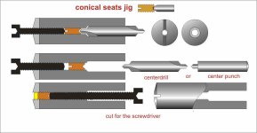
Looking for excuses for not building a TT (...the last thing i will build) i am starting the Lil Casey MK3; beginning from the most boring small parts, such as the eight pen-tip seats. So I decided to finally make a better jig to get them quickly and precisely. (attachment)
A center drill (new) or a diy hardened punch is used to make the seat, then polished using the usual paste and the center drill itself, in reverse rotation. The jig is also used to make the cut for the screwdriver. The most useful detail is the counter screw to block the piece during processing.
Another recent discovery: there is a glue, the so common UHU Extra, which dissolves with alcohol instead of other solvents that damage plastics or paints. Very easy to remove even after a long time without any damaging
Don't expect a great glueing power, but it is very useful to block the cabling of our arms, or to increase the insulation of the very thin enameled ones that we use for the linear ones.
carlo
How boring: improvements have never fascinated me, but in the absence of ideas...
Attachments
Are you using brass for the seats? Do you use stock threaded material or do you make the thread yourself? Wouldn't it be easier to buy some allen pinols and then just make the V in the seats, still using the jig?Looking for excuses for not building a TT (...the last thing i will build) i am starting the Lil Casey MK3; beginning from the most boring small parts, such as the eight pen-tip seats. So I decided to finally make a better jig to get them quickly and precisely. (attachment)
A center drill (new) or a diy hardened punch is used to make the seat, then polished using the usual paste and the center drill itself, in reverse rotation. The jig is also used to make the cut for the screwdriver. The most useful detail is the counter screw to block the piece during processing.
Another recent discovery: there is a glue, the so common UHU Extra, which dissolves with alcohol instead of other solvents that damage plastics or paints. Very easy to remove even after a long time without any damaging
Don't expect a great glueing power, but it is very useful to block the cabling of our arms, or to increase the insulation of the very thin enameled ones that we use for the linear ones.
carlo
How boring: improvements have never fascinated me, but in the absence of ideas...
Yes 2,5 mm stock brass screws, then cut to needed measures. As holder i thread inside some 3,2 mm copper or stainless rivets, cut to measure.
Using pen tips my case is somehow different than using carbide pins: the 118° angle of the center drill is good for me, and I don't need a mirror finish since the rotation is inside the pen tip, not against the seat. What I need (maybe like you) is a perfectly centered seat and for this is crucial the counter screw that avoids completely the screw play while drilling (relevant % with such small diameters) inside the jig's threading .
carlo
Using a good, new center drill helps to get a good finish. Better to make the seat with a hand drill, electric tools are too aggressive
Last edited:
Yes 2,5 mm stock brass screws, then cut to needed measures. As holder i thread inside some 3,2 mm copper or stainless rivets, cut to measure.
Using pen tips my case is somehow different than using carbide pins: the 118° angle of the center drill is good for me, and I don't need a mirror finish since the rotation is inside the pen tip, not against the seat. What I need (maybe like you) is a perfectly centered seat and for this is crucial the counter screw that avoids completely the screw play while drilling (relevant % with such small diameters) inside the jig's threading .
carlo
Using a good, new center drill helps to get a good finish. Better to make the seat with a hand drill, electric tools are too aggressive
I see. I still think that I could use pinol screws ,with the same jig (good idea with the rivets), and just make the seats in them with the center drill.
A lathe would be ok to make the finish, right??
Are you using brass for the seats? Do you use stock threaded material or do you make the thread yourself? Wouldn't it be easier to buy some allen pinols and then just make the V in the seats, still using the jig?
I used M3 cupped set screws these are high tensile. Made a forge from an old drill to make the radius in the Vee. Pins were made from 1.5mm drills cut down.
Then the the whole lot was polished down to 1micron with diamond paste.
Allen pinols are an easier solution for sure: but difficult here to find in 2,5 mm, impossible of brass. To make the screwdriver cut is just a matter of a minute, and shows you the screw tightening position for benefit.
But the needs for the Lil Casey parallelogram with pen tips are quite different from your carriages.
carlo
the jig is made on a lathe of course, but to make the seat a center drill, simply hold in small chuck pushed by hand gives a better feel. The way of watchmakers
But the needs for the Lil Casey parallelogram with pen tips are quite different from your carriages.
carlo
the jig is made on a lathe of course, but to make the seat a center drill, simply hold in small chuck pushed by hand gives a better feel. The way of watchmakers
That makes sense, Thanks.Allen pinols are an easier solution for sure: but difficult here to find in 2,5 mm, impossible of brass. To make the screwdriver cut is just a matter of a minute, and shows you the screw tightening position for benefit.
But the needs for the Lil Casey parallelogram with pen tips are quite different from your carriages.
carlo
the jig is made on a lathe of course, but to make the seat a center drill, simply hold in small chuck pushed by hand gives a better feel. The way of watchmakers
How are you planning to make the rail? New ideas of a non tilting design?
Hi Carlo,
Just wondering, is the VTF of the Lil Casey consistent from outside to inside of the LP, I would have expected VTF to increase as the cartridge moved away from the vertical pivot.
I'm still struggling with my carriage mistracking on off centre pressings, as soon as I get my milling machine up and running again I am going to make a new lighter carriage.
jig sequel
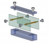
... But once built perfectly centered seats, even more important is the jig to align the threaded supports, just to avoid #3622 - 27 issues ...
Here is mine (attachment): one block grooved to measure + its clamping cover + two threaded bars.
Holes for threaded rivets are drilled 2-3 tenths wider. Rivets, glued with epoxy are then screwed into place. It will be the epoxy to ensure and maintain the correct alignment.
Nothing new, Koldby, I'm slowly trying the #3528 - solution C - that showed promising measures and behavior.
Somehow reluctantly because L C mk2 plays really good, practically with no tilt at all, once set up dynamically for a specific cartridge + VTF. And with the strange feel that often it's easier to go back than forward.
il fren dell'Arte ... we say here
Hi Warren - the Lil Casey is based on two simple concepts, so trivial as to be counter intuitive
the radial rail #2355 - and where should a linear arm rail be positioned? why keep it at a distance?
the parallelogram scale #2384 (well, half parallelogram scale) - Someone calls it "Robertval" (?) but Romans used it 2000 years ago and who knows who else before - no one may joke with the weight of the goods - .
The topic was further discussed with Walter (#3013) in posts #3015-17-19-22-24 with some sketches and calculations.
Attachments
Last edited:
Yes, obviously; but more it shows that wherever the weight is shifted on the plate (= the carriage on the rail) the scale remains in balance because the point of application of the force (ie the lever length) is always the same. This is crucial for a balance, even those with suspended plates work on the same principle.
At the beginning I thought that the full parallelogram scale was needed, then I realized that half of it was enough (4 bearings brings less friction than 6).
Walter had the doubt that this changed the behavior, because he had found some VTF changes on different areas. but the problems came from a wrong rail leveling, not from the carriage position. Read please the discussion starting at #3013 between Walter, Niffy and me. (mockup #3019 - calcs #3024)
ciao carlo
If I am understanding this jig correct:jig sequel
... But once built perfectly centered seats, even more important is the jig to align the threaded supports, just to avoid #3622 - 27 issues ...
Here is mine (attachment): one block grooved to measure + its clamping cover + two threaded bars.
Holes for threaded rivets are drilled 2-3 tenths wider. Rivets, glued with epoxy are then screwed into place. It will be the epoxy to ensure and maintain the correct alignment.
Nothing new, Koldby, I'm slowly trying the #3528 - solution C - that showed promising measures and behavior.
Somehow reluctantly because L C mk2 plays really good, practically with no tilt at all, once set up dynamically for a specific cartridge + VTF. And with the strange feel that often it's easier to go back than forward.
il fren dell'Arte ... we say here
Hi Warren - the Lil Casey is based on two simple concepts, so trivial as to be counter intuitive
the radial rail #2355 - and where should a linear arm rail be positioned? why keep it at a distance?
the parallelogram scale #2384 (well, half parallelogram scale) - Someone calls it "Robertval" (?) but Romans used it 2000 years ago and who knows who else before - no one may joke with the weight of the goods - .
The topic was further discussed with Walter (#3013) in posts #3015-17-19-22-24 with some sketches and calculations.
The two side plates are the ones used in the tonearm. The jig is to ensure that the rivets are glued in place so they are parallel with each other and 90 deg to the plates and exactly in line with the rivet in the opposite plate. Right?
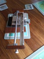
Well, after reading this thread six months ago (and taking 6 months to actually read it all!) I completed a prototype quite quickly (about a week) whilst 'locked down' based on what I remembered from this huge thread.
It's basically a glass railed, two wheeled version, using 12 x 2.5 mm open bearings washed with IPA, and an acrylic / CF sled, fitted to one of my own design / build DD turntables and the thing is IT WORKS!!!
As I said, it's very much a prototype and I'll be building another one based on what I've learned along the way, and leaving out the errors! I want to incorporate pin bearings on the next one, even though the 'washed' bearings seem to work well and move freely with very little stylus deflection (though I appreciate this is also a function of the all up sled / cartridge weight) and I get very little mistracking (I can play whole sides without any skips, and on the rare occasion I do get a skip it's usually contamination of a rail as they're uncovered.
What I would like pointers with if you dont mind is a cueing device. I tried a Rega one as I had one lying around, lifting a CF tube above the cartridge, but obviously the throw isn't great enough. I'm considering an over-centre cam operating a tube which will push down on the rear of the sled. Does that make sense? How have you guys done it?
Anyway, thanks for so much excellent information and guidance, it's been a massive help! Some pics of my prototype attached. The other arm is a 12" unipivot also of my own design, for use when alcohol has been drunk as without a cueing device, the LT is a PITA to cue by hand
An externally hosted image should be here but it was not working when we last tested it.
An externally hosted image should be here but it was not working when we last tested it.
An externally hosted image should be here but it was not working when we last tested it.
An externally hosted image should be here but it was not working when we last tested it.
If I am understanding this jig correct: (.... ....) Right? (Koldby)
Right!
In the L.C. carbon the threaded alignment bar was inserted directly into the support tubes of the pen-tips on the parallelogram levers (that's why the M2,5 mm). This way may be simpler and even applicable to your carriages (schematized in green). Maybe because of my bad lathe (or inadequate skill?) i learned at my expense to rely much more in the matching of parts than in precision up to thous.
For example now I've understood that by pushing the seat in the threaded jig with the counter screw the clearnce is axially canceled by the taper of the threading itself, and this is exactly what happens during use, when it is pushed by the pen tip (mounted elastically).
Seems exaggerated, but at this level of measures a minimal off-center not only grows the friction, but above all makes it irregular, which is even worse.
carlo
apache100 - my welcome to a new LTA builder
What I would like pointers with if you dont mind is a cueing device. I tried a Rega one as I had one lying around, lifting a CF tube above the cartridge, but obviously the throw isn't great enough. I'm considering an over-centre cam operating a tube which will push down on the rear of the sled. Does that make sense? How have you guys done it?
Anyway, thanks for so much excellent information and guidance, it's been a massive help! Some pics of my prototype attached. The other arm is a 12" unipivot also of my own design, for use when alcohol has been drunk as without a cueing device, the LT is a PITA to cue by hand
Great looking arm.
The easiest cuing device is to push down on the back of the carriage. This is a pic of my first arm the 10mm aluminium tube holds the cuing mechanism, which is just mechanical using friction to keep the cartridge up.
Attachments
- Home
- Source & Line
- Analogue Source
- DIY linear tonearm