High Pass Rumble Filter Butterworth 18Hz
Hi Seanc,
Thanks for those graphs. I've attached the circuit diagram of an 8th Butterworth high pass filter that works quite well for rumble. The response plots are quite similar to yours. Look closely at the 10-12Hz region that may well be critical for things that get excited by rumble such as cartridge/arm resonances. OK, I agree that if the turntable has a mediocre cartridge/arm combination then the best thing is to fix the mechanical problems and after that try electronic remediation.
It uses one quad opamp per channel which is handy for channel separation reasons. The layout is very symmetrical - all the caps are the same and all the resistors are parallel pairs. I use "Veroboard" (that's what it is called in the UK and Commonwealth) which is quick but might be sub-optimal from a layout perspective. I reckon if it works on Veroboard, it can only get better with proper routing software and PCBs!
Attachments
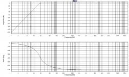
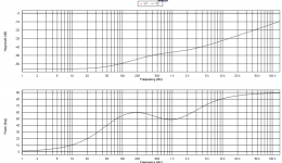
With Rod Elliots topology, faster rolloff is possible using alternate part values, at the expense of 50% more group delay at 20Hz (37mS vs 23mS).
Adjusted to be the same 2dB down @ 20Hz as Elliots. Much better in the 8-12dB range. This graph optimized with 85nF caps, a non-standard film value. Purple trace uses Rod Elliots values, Green trace is with alternate values:
View attachment 828287
Similar results can be obtained using standard 82nF & 91nF caps (Elliots values in Yellow):
View attachment 828288
In my builds, I used 100nF/0.1uF caps, and the result was fine.
The vertical filter is implemented through a second order differential Bessel filter set to 140Hz.
What do the responses with only one channel driven look like, for example left to left and left to right?
Phono Preamp with Input Z Synthesis
The phono stage owes a lot to Stan Curtis who founded and ran some really famous and successful audio companies. If you can, find some of his articles and see for yourself that Stan has a really great way of explaining complex ideas in a way that makes sense. I'm sure that if he was to concentrate on this today, he'd find some clever ways of improving and "productionizing" it.
The top part of the circuit is an Inverse RIAA Circuit (i.e. produces the RIAA Pre-Emphasis). NOTE: this does NOT produce an approximation to the RIAA curve - it is absolutely spot on. There are several passive circuits out there: Williamson, Lipshitz, Bazendall, etc. None of them is EXACT. Why? Because it can't be done passively! Seriously, try it out and compare the simulations with an EXCEL spreadsheet implementation of the RIAA equations.
The bottom part starts with a G=+20 stage designed to partially lift the signal out of the noise. The input Z synthesis is quite easy to understand. Check the input impedance in your simulations and it will come out at 47K -as advertized.
The next stage implements the 75us time constant and provides a gain of -10. The 7.5n cap is easily made by putting two 15n caps in series.
The final stage "de-shelves" the response with the 318/3180us circuit. R13 is 9 times the value of R14. R14 times the sum of C5 and C6 = 318us. R13 divided by R12 is 10 and because the stage is inverting, the Gain = -10.
The circuit is actually very simple with no odd-ball values. Note that the highest gain is in Stage 1 (Gain = +20). Stages 2 and 3 each have Gain = -10 so that the overall gain is +2000. None of these ams should show any stress due to running out of loop gain. This is perfect for the majority of moving magnet cartridges that produce 5mV at 1 KHz (and only 0.5mV at the lowest frequencies).
Look at what the circuit does by placing probes at each stage. You can get a good idea what the overload margins will be.
Someone mentioned being able to model the noise produced by the amps. It would be really interesting to see if the character of the noise and its absolute levels really differed between the all-in-one-go non-inverting designs (the vast majority of designs out there) and the split inverting designs (like this one).
Do any of you have any thoughts about electrolytic capacitors in the signal path? Doug Self seems to use them with impunity so I wonder if some of the negative opinions about electrolytics are overblown?
Attachments
I'd be tempted to push the cap values upto 220nF or 470nF so lower value resistors can be used keeping the Johnson noise down and mitigate the effects of opamp current noise if bipolars are used.
I did a DIY project a couple years ago that used 220n caps and common (e24) resistors: DIY 18Hz HPF Vinyl De-Rumbler filter
I used OPA4134 opamps (FET input).
I'd be tempted to push the cap values upto 220nF or 470nF so lower value resistors can be used keeping the Johnson noise down and mitigate the effects of opamp current noise if bipolars are used.
That wouldn't do any harm, obviously, but I don't believe it is really needed either.
The total RMS thermal noise across a capacitor with capacitance C is sqrt(kT/C). For 100 nF at 293.15 K (20 degrees Celsius), that boils down to 201.18 nV.
The resistance of the resistors that generate the noise that the capacitor integrates just influence its spectral distribution, not the total RMS value. In a filter, most of the noise will be at frequencies up to the cut-off frequency. In this case, those are subsonic frequencies and low audio frequencies, at which human ears are not particularly sensitive.
For comparison, over a bandwidth of 13 kHz, which is roughly the noise bandwidth of an A-weighting filter, a series resistor of 192.31 ohm also generates 201.18 nV of noise - but that would be noise spread evenly over the band, so also at frequencies where your ears are most sensitive. As the subsonic filter / vertical filter is placed after a RIAA amplifier with a considerable gain, noise levels of this order of magnitude should be negligible.
The op-amp's current noise may aggravate things somewhat. Suppose it is 0.6 pA/sqrt(Hz), the datasheet value of an NE5532. Across the series connection of three 100 nF capacitors, that produces a noise voltage density of 2.8648 nV/sqrt(Hz) at 1 kHz. It goes up at lower frequencies, but there the A- and ITU-R 468-weighting curves go down quite steeply, and down at higher frequencies.
You can compare the op-amp's current noise to the noise current of the filter resistors to get an impression of its contribution to the total RMS noise. 0.6 pA/sqrt(Hz) is the amount of noise current that a shunt resistor of 44.971 kohm produces at 293.15 K. The filter resistors are of the same order of magnitude, so the total RMS noise may go up by about a factor of sqrt(2) or so compared to the sqrt(kT/C) equation.
What companies does Stan Curtis reckon he founded and ran?
Dear Sawyers,
Have a look at these links:
hificritic.com/curtis.html
Stan Curtis, Engineer, introduction to my website particularly at Career Highlights
Author | Linear Audio
Stan has moved all over the world with his business interests but, I think, now lives back in Cambridge. As does Doug Self. Your profile shows that you live near Oxford?
Do you know Stan or Doug? I only know them by reputation and their publications, and the odd email exchange.
Are you in the audio business? I am an engineer (medical devices) but wish I'd gone into audio. It would have been a haphazard existence but always exciting!
Apparently Douglas Self corresponds with a lot of people. I used to correspond with him by normal paper mail in the mid-1990's, mainly about audio power amplifiers and noise optimization of RIAA amplifiers for moving-magnet cartridges. In fact I pointed out the importance of amplifier current noise and cartridge inductance to him.
Sadly you cannot unsend email notifications so we all got your views on Stan!
Ah - well whatever, it seems to have gone. But yes - I do have strong views on this subject.
Phono Derumbler Performance
I built the derumbler and test fixture last week and could see that it appeared to work on my old analog TEK scopes (designed and built by geniuses!).
My new 4-channel DSO arrived a day early from Amazon so I set it up yesterday. And, yes, the derumbler still worked!
The first screenshot shows a 1KHz sine wave below with the FFT spectrum above. The input is as shown in the second shot. The rumble is completely suppressed.
The second shot shows the input to both channels. The waveform is the same 1KHz modulated with 20Hz hum. The spectrum shows both signals at an amplitide of 1V.
The third shot shows what happens when the rumble is in phase (like horizontal rumble). The image looks identical to the second because the derumbler only works on vertical rumble.
My next job is to try two completely signals for the left and right channels (I'll try sine and triangle) to show the effect of mono-ing the signals below 150Hz. I'll also drop the "rumble" to 10Hz.
Watch this space!
Attachments
I'd also like to offer that both Wharfedale and Quad are massively stronger now as part of IAG than they were in blighty. My involvement with Wharfedale was in the early 90's was when it was really bumping along the bottom. The only way I could lead the programme of product development was using petty cash to buy bits over the counter at Farnell for folding money.
Wharfedale and Quad products now fight their corner with the best, and Quad still have their superb service centre and support in Huntingdon. The electrostatic speakers from IAG are, from what I have heard, truly superb.
Am I sad that these iconic British brands now aren't British? For sure - but we as an audio industry simply could not make them into a long-term viable business. So thanks to Stan Curtis for making sure that they have a good future.
Back on topic, I use Linkwitz LX521.4's. Included in the active crossover I have included (a) a modified Quad tilt circuit (generally lower R's and higher C's to reduce circuit noise) and (b) because I listen mainly to good old vinyl, a Douglas Self DeVinyliser. We've discussed the pros and cons of that circuit, but that is what I've gone for.
Back off topic, and still trying to put the record straight after my boozy cabin-fever mail yesterday (that I thought I'd managed to delete quick enough).
1. Stan Curtis was Chairman of IAG until 2000, strongly suggesting that he indeed was a co-founder.
2. From a Steve Harris interview in the audio press with Mission founder Farad Azima "'In the early days,' Farad recalls, 'Stan Curtis joined me and designed some amplifiers and stuff." So Stan Curtis was responsible for the very first Mission electronics products, and in fact pre-dates Farad's brother Henry Azima joining the company.
3. Stan Curtis was certainly involved in the early days of Cambridge Audio. And was increasingly involved, running the company through some very difficult times.
4. As mentioned above, Curtis saved Wharfedale and Quad from near certain death, and ensured that both brands are strong and with superb products within IAG.
While I'm here reminiscing about Cambridge Audio, three years ago in order to celebrate 50 years since Gordon Edge founded the company, they introduced the Edge series of electronics and loudspeakers. Gordon's barely legible signature is silk screened on each circuit board. Edge Series - The pinnacle of 50 years of Hi-Fi expertise. | Cambridge Audio
I curiously checked out that Cambridge site that sawyers posted.
Particularly that "Edge" series.......
I have to say, the fancy marketing is typical of manufacturers pushing their snazzy and price-bloated equipment.
Ho-Hum, and inspecting the advertised specs, it's really not much different than my 1989 era Technics components with specs that were reached decades ago - I suspect that the new, current, non-educated curious audiofools would not suspect the fact that you can only refine performance only so far.
But the visually impressive cladding naturally makes something "better", as eye-candy usually does, as does the series name.... "Edge", leading one to think they have "the edge" on performance. - tricky marketing at its finest.
It reminds me of the 1950's automobile styling - as bigger and bigger fins on cars arose, while the engines stayed the same.
Nevertheless, it cracks me up that on the rear panel, "Assembled in China" is shown, and all yours to enjoy for a mere several thousand dollars.
Thanks, but I'll stick to my "lowly" Technics stuff, with its hideous black facades, and enduring reliability and top notch performance.
- Status
- This old topic is closed. If you want to reopen this topic, contact a moderator using the "Report Post" button.
- Home
- Source & Line
- Analogue Source
- The ultimate rumble filter - far more effective than just a high pass filter!