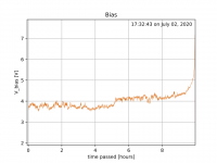
I have a question regarding stability of the bias in UFSP, as measured across R4. I had problems to find a reproducible precise setting for one of the channels, and decided to run a longer-term monitoring over a few hours -- see below.
This is from taking measurements every 5sec for the past 10h (using a little Arduino), and as one can see the bias is wandering around by around half a Volt or so.
I don't think this is related to temperature, so I was kind of surprised.
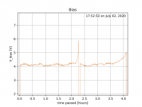
The other channel is much more stable (second plot).
I was wondering, should I be worried about this or does this have no impact on performance?
This is from taking measurements every 5sec for the past 10h (using a little Arduino), and as one can see the bias is wandering around by around half a Volt or so.
I don't think this is related to temperature, so I was kind of surprised.
The other channel is much more stable (second plot).
I was wondering, should I be worried about this or does this have no impact on performance?
Attachments
Hi, it is related to localized temperature and it's normal for this kind of fets in this design. Just blow air with your mouth on Q1 Q2 and you will see a V jump.
Such high yfs low vgs (off) fets are inherently self running away especially at the high Id low Rs values necessary in lmc/mc mode to minimize noise contributions. I had tried active constant current sourcing instead of drain resistors to harness them but noise went unacceptably high.
If you select a lower sensitivity mode like hmc/mm it gets tighter because of the higher source pin resistor's value bringing more local feedback stabilization. A luxury not affordable in my lmc/mc modes noise budget.
In conclusion, that's how it works don't worry. Actually it works better in your graphs than in some past builds.
T.P adjustment works here for DC level centering. If you will measure voltage between drain and source of your Q1 Q2 it should be about 8V DC. Maybe 7.8V or something. Not important. We just set T.P for half that i.e at about 4V.
Imagine a car speeding on an 8 lane empty motorway steering not dead on but about the center line. Because bit idiosyncratic. Each lane is a Volt. Left and right to the car's course it is all free space for AC signal swing. Which is few hundred mV tops in this case. What you basically want is not let it drift and crash at any side of the motorway. Nor to let it come close enough to any one side for clipping the signal peak it carries. But some mid-line wobble is no problem when on such a wide empty motorway.
Imagine a car speeding on an 8 lane empty motorway steering not dead on but about the center line. Because bit idiosyncratic. Each lane is a Volt. Left and right to the car's course it is all free space for AC signal swing. Which is few hundred mV tops in this case. What you basically want is not let it drift and crash at any side of the motorway. Nor to let it come close enough to any one side for clipping the signal peak it carries. But some mid-line wobble is no problem when on such a wide empty motorway.
I did not experience with such swing in my Ult build. I monitored TPs over 2-3 days (about once in hour) and 4V BIAS was very steady with closed lid. Any internal movement or lid removal caused change, but that behave was expected. My box is taller and probably less temp-conductive due to thick wood side-boards.... It is quite steady with internal temp equilibrium and I did not see changes after about 3 hours of On time. Have you shorted inputs?
Open box is naturally more affected by small ambient room temperature changes or weak air drafts. Then the wobble graph paints a more sinister picture of that motorway trip. 
Jah Wobble's Invaders Of The Heart ~ Rising Above Bedlam
Jah Wobble's Invaders Of The Heart ~ Rising Above Bedlam
4V BIAS was very steady with closed lid. Any internal movement or lid removal caused change, but that behave was expected.
I remembered to try my cheap Pro'sKit MT-2017 analog meter yesterday, and you know what? Not only its Hfe measuring of TO-92 transistors was in the right zone but also watching DC fluctuations on its needle was more natural to monitor their swing. You don't get DMM accuracy, ok that's understood, but with just a glance you know if things are alright and how important a deflection is as a percentage. No decimal digits dancing party to watch.
Also no battery power is used up for voltage readings on a needle meter, so someone can hook it up and watch over something forever.
Folks:
I’d like to extend my heartfelt appreciation to Salas and Tea-Bag for making the Ultra FSP available to the masses (okay, to the diyAudio community)! My old phono preamp, a Pearl / Ono project completed in 2007, was getting a little long in the tooth and I had been looking forward to updating my phono system. The Ultra FSP project came along at exactly the right time.
This was an easy build. Salas’ instructions are clear and there really isn’t much to mess up. The project went together beautifully. Tea-Bag is clearly suffering from OCD – his parts were well organized, complete and matched to a degree that I could never hope to achieve. You guys made this easy and I really am grateful for your generosity.
I’m currently listening to Shine, off Be Bop Deluxe’s Live In The Air Age album. I fell in love with this song in 1977, when the album was released, and have used it to judge engagement, depth and pacing on every new piece of audio gear I’ve since built or collected. Honestly, it’s never sounded better. That’s the highest praise I can offer, and Salas’ UFSP is clearly the reason why.
Again, many, many thanks!
Regards,
Scott
Attachments
meanie:
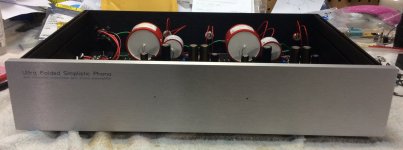
Thank you! My design goal, at least as far as cosmetics are concerned, is to make my projects not stand out as home-brew gear. It's weird, but I frequently don't tell people who listen to my system that I built it. If the gear looks commercial, my guests assume it is and we don't spend time talking about the equipment. Instead, we just listen to the music.
Regards,
Scott

6L6, katopis and donhughes111:
Thank you for your kind words. If you guys ever find yourself in the Philadelphia, PA region, drop me a line. I'd be happy to invite you over for a beer/glass of wine/stiff drink (or more) and some time in my basement dungeon.
donhughes111:
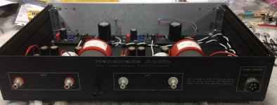
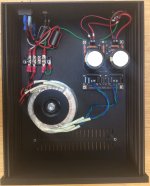
Both enclosures are 2U in height. The power supply is a Galaxy chassis, 230mm by 280mm, and the UFSP is a Slim Line 450mm by 280mm chassis (3mm aluminum top and bottom). Clearly, I could have gotten away with 230mm deep boxes but I like having some breathing room.
Regards,
Scott
Thank you for your kind words. If you guys ever find yourself in the Philadelphia, PA region, drop me a line. I'd be happy to invite you over for a beer/glass of wine/stiff drink (or more) and some time in my basement dungeon.
donhughes111:
Both enclosures are 2U in height. The power supply is a Galaxy chassis, 230mm by 280mm, and the UFSP is a Slim Line 450mm by 280mm chassis (3mm aluminum top and bottom). Clearly, I could have gotten away with 230mm deep boxes but I like having some breathing room.
Regards,
Scott
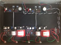
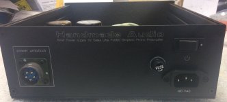
Absolutely, thanks. To some tech details now, I see you avoided main chassis reference through the RawPsu Yin Yang diodes//10R lifting. Instead, after mating the boards zeros at the main chassis gnd lug on back panel, you continued through the floor all the way to the mains earth at the PSU box via the green line in the umbilical. Correct?
There are various ways to route chassis refs and differently earthed TTs or whole systems may prefer one or another. Is it all quiet with yours?
Also, is it a 56dB gain and a 47k loading you set? Not sure when trying to understand from the photos. What TT and cart model you use?
CMR 2.2uF C4 could have been their 400V type for slimmer body but the 630V managed to also sit. What C2Y value you settled for?
Salas:
You've got sharp eyes! Yes, the ground is laid out as you noted and it's quiet with two exceptions: (a) with the interconnects that ordinarily run between the UFSP and the turntable disconnected from the turntable, there is a far louder hum and the cables become microphonic; and (b) I struggled for a few years with a very low level popping sound when using my prior phono amp and that sound persists with the UFSP.
I'm not sure if (a) is commonplace and it certainly isn't an issue under normal circumstances, but I wonder if it is evidence of an issue that could be corrected. And I have no idea how to address (b), as swapping interconnects and changing grounding schemes in the past hasn't affected the problem. That said, if you have any suggestions on how I might revise my UFSP grounding scheme, I would be pleased to try them out.
My turntable is a Maplenoll Apollo and the cartridge is a Lyra Lydian Beta that was recently rebuilt by SoundSmith. The Lydian has an output of 0.7 mV. I could certainly raise the ante on the UFSP by increasing the gain to the highest level, but the current setting is (without having compared it to its alternatives) working fine.
Although I certainly appreciate the fact that a 400V cap would be capable of handling the demands of the UFSP, past experience has suggested that the larger caps often sound slightly better. Consequently, I decided on the 630V CMR caps.
I used the 220pf caps that Tea-Bag supplied at C2Y. Together with the supplied C2 caps, the total was just a hair over 15.2.
If you have any advice, please don't hold back!
Regards,
Scott
Scott hi,
Open ended TT cables become antennae to the preamp's high sensitivity inputs, especially when on 47k load, so that thing might not have something to do with your earthing scheme. If you short the open ends between hot and ground for each channel they should become quiet.
That years old popping sound is it periodic? Sounds like static? Something to do with mains filtering or mains ground needed on the TT's PSU case maybe? Pump motor producing some pulses?
Other tested earthing schemes to possibly try are a. The one described in post #17797 and used in most FSP builds, b. The one from Alex reported working well with his non metallic TT and arm in post #17902. The raw psu board has two diodes safe lift and resistors network already so not necessary to also use the full bridge he had shown there. You can just wire to the mains earth connected psu chassis lug from the PE --E pad instead.
Your TT is heavy league parallel tracking that must be awesome when running as it should, complex things the parallel trackers with air pumps etc. Your choice of 56dB gain is excellent for 0.7mV output. 62dB if applied will give more oomph but it will certainly push THD higher in the preamp. Dominant 2ndH will be mostly felt. Because SE JFET. Won't break anything if you will prefer that tone anyway. Losing some dB of headroom for very loud clicks on bad discs.
C2Y choice seems close in line with the other early reports. If not soldered but on sockets you may recheck it vs nearby values after 50 hours of play.
Salas:
Thanks for the prompt response! I'll try out a few of the other earthing schemes you referenced and will report back.
Aside from the two small ferrite cores I installed at the power supply's IEC inlet, there isn't any mains filtering in the UFSP build. I did install a small filter on my old Pearl / Ono phono amp but that did not affect the popping sound. The popping sound, which might include a static component, is evident regardless of whether the turntable or its pump are turned on. The sound is persistent but not continuous (i.e., there are brief moments of silence followed by a pop or three and then silence again, but the popping is always there).
In general, I follow the engineers' creed ("if it ain't broke, don't fix it"), so while I might test the higher 62 dB gain setting I'm more inclined to keep the noise floor as low as possible.
Regards,
Scott
- Home
- Source & Line
- Analogue Source
- Simplistic NJFET RIAA