If you have separate, non-coupled inductors in a design, and you put phase dots on them, you incorrectly specify them as transformer coupled inductors.
You are 100% correct Mark, they make sense ONLY for coupled inductors to indicate relative phase or, as we at Philips used to say, Start Of Winding.
Jan
You are 100% correct Mark, they make sense ONLY for coupled inductors to indicate relative phase or, as we at Philips used to say, Start Of Winding.
Jan
I received this note in a private message. However, because I believe that 250,000 heads are better than one, I am copying it here so the entire membership of diyAudio can share their knowledge, opinions, and personal experiences. Please read and reply if you have a contribution to make or a thought to share.
In the EE curriculum when I was at university, we only used "polarity dots" when drawing schematics that have two (or more) mutually coupled inductors. Those dots indicated which end of each inductive winding have in-phase outputs, and we called them "phase dots". We never put those dots on individual inductors. Only on transformers and loosely coupled inductors like electromagnetic actuators. So I myself have no idea what the question even means. If you do, please speak up.
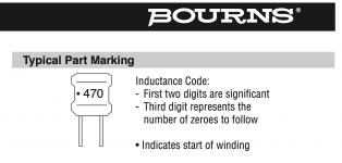
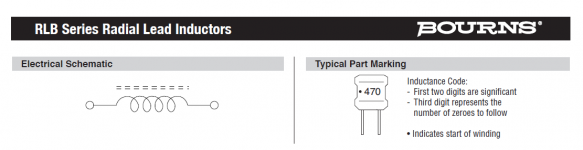
You learn something every day - or most times I read threads on diyaudio! The Bournes inductors we specified for the original BOM (and that I included in the kits) do include a dot to orient the start of the winding. I never noticed this before but when I just checked the sheet its right there in the description of the label:
https://www.mouser.com/datasheet/2/54/rlb-777833.pdf
--Tom
Attachments
Last edited:
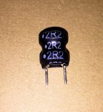
Yep, I found my original Mouser parts bag, shook out one of the inductors for this project, and snapped a picture. Sure enough, the manufacturer Bourns does print "start of winding" dots on the sleeve.
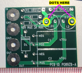
Fortunately, in this DC power supply application using "Ferrite DR" material for the inductor core, there is no significant difference between the two possible positionings of each inductor. Either Dot-on-Positive-terminal OR Dot-on-Negative-terminal is perfectly acceptable in this application. It makes no difference at all, which you choose.
However, for those who seek a concrete & specific recommendation, here is mine: I recommend installing the inductors such that the dots on the sleeve are connected to the terminals colored yellow in Figure 2 below.
_
Attachments
Last edited:
I received this note in a private message. However, because I believe that 250,000 heads are better than one, I am copying it here so the entire membership of diyAudio can share their knowledge, opinions, and personal experiences. Please read and reply if you have a contribution to make or a thought to share.
In the EE curriculum when I was at university, we only used "polarity dots" when drawing schematics that have two (or more) mutually coupled inductors. Those dots indicated which end of each inductive winding have in-phase outputs, and we called them "phase dots". We never put those dots on individual inductors. Only on transformers and loosely coupled inductors like electromagnetic actuators. So I myself have no idea what the question even means. If you do, please speak up.
I hope everyone saw Tom's message but in case not, here it is again, in bold italics.
I wanted to update folks that the kits are now available in the store!
SMPS DC Filter P089ZB Kit – diyAudio Store
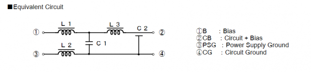
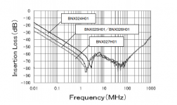
Take a look at following COTS Filter for DC : MURATA BNX026H01 : BNX026H01(BNX026H01B,BNX026H01K,BNX026H01L)|Block Type|Noise Suppression Products/EMI Suppression Filters|Murata Manufacturing Co., Ltd.
So power chain to have a clean power supply for audio circuits :
PS Wall AC-DC -> Filter BNX -> LDO regulator.
If others DC voltage are necessary (or dual voltage) a switch regulator between BNX and LDO is a solution. TI Power modules like LMZ14203H or equivalent have a very low ripple voltage at the output. By adding a LDO after the switching regulator, you will have a very clean power supply for audio circuit.
I wanted to update folks that the kits are now available in the store!
SMPS DC Filter P089ZB Kit – diyAudio Store
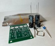
Looks like an excellent bargain! USD 9.00 for all of this:
_
Attachments
Last edited:
Someone bought from Italy, do you know the duties to pay?
Sorry, I don't know.
Take a look at following COTS Filter for DC : MURATA BNX026H01
Thank you for calling attention to that component! Although Mouser does not sell it, DigiKey does. AND they have 6200+ pieces in stock, on the shelf, today:
LINK
")
I wanted to update folks that the kits are now available in the store!
SMPS DC Filter P089ZB Kit – diyAudio Store
Dang, I have two sets of parts but no boards, and the board I am after is one with four mounting holes spaced identically to the holes on an RPi: 5.8cm by 5cm, it looks like, so I can stack this filter as the third layer. The diyAudio listing doesn't give the hole spacing measurements nor do the boards appear to be sold bare, and no I don't agree that a diy run of 20+ of these is appropriate use of the world's resources when one really only needs 1 or 2.
But also, my ideal solution would be a board with solder points for a surface mount USB-C receptacle as the DC in. Decisions, decisions.
It's an excellent "my first PCB layout" project! Very few components, all thru hole, only two layers. Go ahead and create a version that does exactly and precisely what YOU want! You'll have fun, you'll learn a new skill, and you'll have the option to make appropriate use of the world's resources by purchasing only 3 of them (from OSHPark).
ranshdow:
JLCPCB will do 5 boards for less than $9 including standard shipping to the USA. Just lay it out in KiCad and plot the gerbers. It's a very simple circuit. Current sense resistors are 12mm pad-to-pad with 1.3mm drill hole. Note the cathode (K) on the TVS devices and correlate with the data sheet.
JLCPCB will do 5 boards for less than $9 including standard shipping to the USA. Just lay it out in KiCad and plot the gerbers. It's a very simple circuit. Current sense resistors are 12mm pad-to-pad with 1.3mm drill hole. Note the cathode (K) on the TVS devices and correlate with the data sheet.
Thanks for the suggestions, both. If I want to go overboard on my first attempt and have it come with a USB-C receptacle already soldered, that would do it for me. I've seen at least one of the diyaudio boards for sale that looks like it come with the smt devices already on them- Wayne's burning amp thing I think.
I suppose these are the (most) relevant pieces of information from this spec sheet.
Knowing nearly nothing, I'd wonder looking at this that these devices don't have any protection against resonance (I mean oscillation) like Mark's design does, nor does it have any diode protecting the circuit from flipped polarity. I don't recall what the frequency response/attenuation characteristics of Mark's design is either, something about 65MHz cutoff maybe (I thought this was basically a low-pass filter)?
(edits in parenthesis)
Attachments
Last edited:
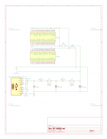
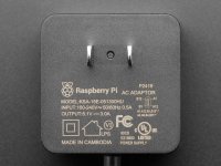
I think this is what I want, it's pretty simple- basically a PO89ZB circuit which takes input power from a USB-C receptacle fed by an official 5.1V 3A RPi wall wart. The filtered power output of the PO89ZB is then fed into the 40-pin HAT expansion board headers at appropriate pins, with the option on the PCB for a header in either the standard HAT location or the expansion board location. I want jumpers to be able to disconnect both power and ground from the HAT headers in case there is an issue. There will be a separate 2-pin header that will always be live, for power monitoring or direct wired connection to elsewhere on the RPi or expansion boards (the unterminated wires).
You may notice I'm taking all four of the USB-C lines (A4, A9, B4, B9) marked as "+" on the wall wart as power in to the PO89ZB, and all four (A1, A12, B1, B12) marked as "-" on the wart as ground. Also I'm feeding more than one, but not all, of the P5V and GND pins on each HAT header with the output of the PO89ZB. I don't know if this is kosher or not. My thinking is it shouldn't hurt to have parallel input and output paths.
Anyway, if anyone sees anything gross on this before I attempt to figure out part sizes and lay out the PCB, or have other suggested functionalities, I'd much appreciate it. Also if anyone knows an outfit that would both make the PCB and mount the USB-C receptacle (I'm pretty sure these are all SMT and I have zero experience with that), that would be awesome. Thanks for reading, thanks avdesignguru for the hints and the nudge to get me to try this (my first!), and thanks so much Mark for making such a useful filter.
Attachments
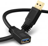
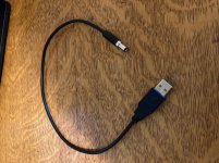
Maybe it might make your project a little easier if you used an inline USB jack for cable-to-cable inline connections. Then you don't need to find or create a PCB footprint, you don't need to source the component, and you don't need to stuff and solder it into the board.
Amazon sells USB Extension Cables for $6 such as the one in the photo below. Cut the cord midway between the jack and the plug, strip the external protective jacket and the individual wires, and then just solder them to plain ordinary holes in your PCB. And of course provide a mechanically safe, strain relieved, passage from outside the chassis to inside the chassis.
_
Attachments
As a hack, sure but I'm going for a little higher quality implementation this time around. Also an exercise in design and fab for me. There are so many little e-parts out there with high production value, it would be nice to see if I could pull that off. Been doing the spliced cable thing for the testing I did; the final result on my B1 Korg is hidden & clean.
Attachments
- Home
- Source & Line
- Analog Line Level
- PO89ZB , an inline DC filter for SMPS wall warts . Preamps, HPA, Korg NuTube, etc