> insert a 1 milli-ohm resistor in series .... That makes the current into the input port easily accessible within LTSpice.
Hmmm. I've only spent a day, but LTSpice happily plots current. I know because I tested my pot, not with the suggested current source, but with a voltage source. V1/I(v1) directly gives mag(Z).
In PSpice, yes I sometimes need a dummy part to poke current (more with tube/transistor), but when you plot a V/I the scale shows "Ohms" (a meaningless frill).
> tutorials on how to create your own pot...life is too short to waste hours struggling
I am typo-checking a writer's manuscript. It describes creating a part, symbol and code, and the example is pot. The writing is quite clear; but the process IS too tedious and error-prone for my small mind. My comments here:
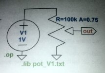
--- OK. Two hours to get a pot model working. One screw-up is I typed "pop" instead of "pot", duhhh! Also got out-of-order in the lines on page 25, duh. Mildly compounded by refusing to name the pins in-out-common, trying 1-2-3, then top-wip-bot, but that was not the issue. Also ignored zig-zag artwork for a simple box with sidearm, which is fine. Parameters R and A pass-through properly. Works for .AC. Found how to list 2 (3?) parameters as list instead of line.
And the cheat to avoid the /0 error for A 0 or 1 is:
R1 top wip {((1-A)*r)+gmin}
R2 wip bot {(A*R)+gmin}
(gmin is a very small number, default 1e-12.)
Alternatively for "real" pots it would be realistic MIN/MAX to 0.99 or 0.01, since pot end effect runs about 1%. But for "ideal" potwork this leads to mystery discrepancy ("why is it 0.99 instead of 1.0?"). Using gmin puts the error in the numeric noise. ("0" makes wiper -300dB, which is quiet enough.)
Hmmm. I've only spent a day, but LTSpice happily plots current. I know because I tested my pot, not with the suggested current source, but with a voltage source. V1/I(v1) directly gives mag(Z).
In PSpice, yes I sometimes need a dummy part to poke current (more with tube/transistor), but when you plot a V/I the scale shows "Ohms" (a meaningless frill).
> tutorials on how to create your own pot...life is too short to waste hours struggling
I am typo-checking a writer's manuscript. It describes creating a part, symbol and code, and the example is pot. The writing is quite clear; but the process IS too tedious and error-prone for my small mind. My comments here:
--- OK. Two hours to get a pot model working. One screw-up is I typed "pop" instead of "pot", duhhh! Also got out-of-order in the lines on page 25, duh. Mildly compounded by refusing to name the pins in-out-common, trying 1-2-3, then top-wip-bot, but that was not the issue. Also ignored zig-zag artwork for a simple box with sidearm, which is fine. Parameters R and A pass-through properly. Works for .AC. Found how to list 2 (3?) parameters as list instead of line.
And the cheat to avoid the /0 error for A 0 or 1 is:
R1 top wip {((1-A)*r)+gmin}
R2 wip bot {(A*R)+gmin}
(gmin is a very small number, default 1e-12.)
Alternatively for "real" pots it would be realistic MIN/MAX to 0.99 or 0.01, since pot end effect runs about 1%. But for "ideal" potwork this leads to mystery discrepancy ("why is it 0.99 instead of 1.0?"). Using gmin puts the error in the numeric noise. ("0" makes wiper -300dB, which is quiet enough.)
Attachments
Last edited:
Excellent, I didn't realize you could access I(v1) directly. Thanks!V1/I(v1) directly gives mag(Z).
Thanks for the tip about gmin as well.
The log-pot equations I came up with do not go exactly to zero resistance at zero rotation, because of the nature of the exponential function. I think one side of the pot goes to 1% of total resistance when the pot is turned to that end.
Real-world log pots apparently aren't actually logarithmic / exponential, but made up of as few as two straight-line segments with a kink where they meet. Straight lines can be coaxed to go to zero at zero rotation, where exponential functions cannot.
-Gnobuddy
The e/bay board need a dual output transformer. I used the Antek toroidal transformer. They are very quiet and shipping is cheap. (I had some very bad experience with e/bay ordered transformer.) The current requirement are very small for the 5 op-amp onboard. A 25VA or even 10VA transformer is sufficient.I focused on ngspice last night, going through their resources pages. It seems to be a mature simulation engine and the good thing is that it is integrated in more complete software packages that provide luxuries like schematic editing. I started downloading eSim and KiCad last night but transfer was interrupted due to a battery outage. I 'll try to build the same circuit for the LR crossover in both of them, see how well they work (or not).
Speaking of the LR crossover, I decided to snatch a cheap implementation of it for further experimentation. Sadly, the good people in the far east that sell it seem to not know what they are selling:
View attachment 776268
My specific query is about powering the unit. Their product description states:
"8. AC adapter power supply range Dual 14 to dual 19V"
Now, I can not understand if this means a regular center-tapped-secondary transformer (+-15V AC) or simply +-15V DC.
Can you guys tell by the looks of this board which case it is? Because honestly I do not expect a reliable answer from the seller. If the power input is +-15V AC there should be additional components for DC conversion to feed the opamps.


The onboard power supply is perfectly fine and very quiet. I replaced the IC with LME49720, but the NE5532 works fine too. It is a very good, inexpensive way to play with Linkwitz-Riley crossover.
One thing missing is the level (volume) control for individual bands.
Last edited:
I have one of this completely assembled box at 2800Hz crossover frequency. I like the quality of its box, much heavier than most sold alone aluminum exclosure on e/bay. Overall it works very well. The nice thing is that it has master volume control plus individual output band level controls.Given things on the board are as you suspect, it's just as I imagined. Substitute AC with DC, just with a different amplitude.
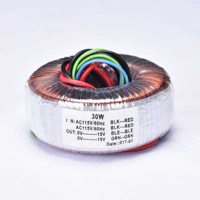
I found a completed LR product there in the far east, and zoomed into it's toroidal transformer:
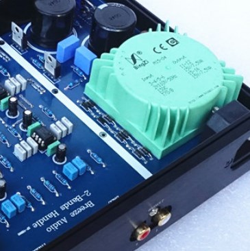
And further research shows it's this, it's a PCB mounted version:
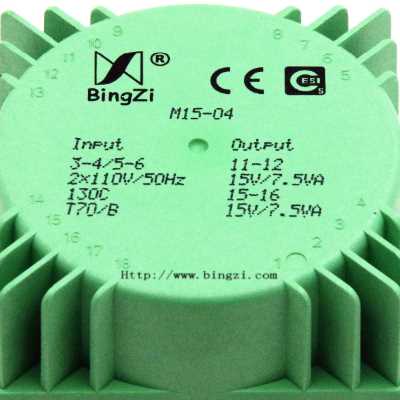
So the people in the far east are using a 15VA transformer. Perhaps they are aware of noise problems at lower power ratings. Perhaps it costs the same to make a 10VA transformer. I trust you guys however, in that this board's demands are nowhere near 15VA.
This green thing costs something like 20$. I almost got it until I found a different toroidal, 30VA mind you, for something like 13$ so I just snatched it. If it works, cheap is good in this case:
It has a dual primary winding so I imagine I have to very carefully connect them in series so that it properly works in my country (Greece, 230V-240V) and nothing blows up.
So I am super excitedly waiting for these two components to play with.
A final note: After your earlier calculations about the board's current draw, I had my reservations because of the text from ESP's power supply description: "If a split AC supply is used (such as 15-0-15V AC), then the transformer centre tap connects to GND, and the two 15V winding ends connect to AC1 and AC2. Although virtually any transformer of 0.5A or more will work (provided the voltage is correct), there is very little to be gained by using anything more than 30VA (and even that is likely to be overkill)."
I think my mistake is that this is a description for a generic power supply for preamplifiers. Other boards may have much higher demands, hence the high-ish 30VA rating he recommends (ten times what I need in this case). Regardless, I ended up getting a 30VA after all, just because of the price.
As a second side note, and because LR is pretty much finished in this thread for now, I am installing eSim and KiCad and attempting to recreate/simulate the same circuit I made in LTspice. See if and how things work out. 🙂

Last edited:
I just noticed that you are in Swiss so the Antek transformer Co. may not work for you. If you order small power transformer from e/bay, the R-core one is much safer, in term of hum leakage, than the toroidal from China. In theory, they should be both good and I personally like toroidal better. But I am talking about quality control here.Hello all,
I'm Yanni, new to this forum, and new to the audio electronics "disease". The bug stung very recently but it was one nasty sting. I didn't expect that. I thought registering in an appropriate internet forum would be a great idea. The name and looks of this one seemed the best, cause there's more than a few out there.
Now as to why I'm making my first post here: I need some frequency response curves for the Linkwitz-Riley crossover, 24dB/octave version. I need 5 graphs, for 60Hz, 70Hz, 80Hz, 90Hz, 100Hz crossover frequencies, or as many of them as I can get. It's important that I have a vertical window of 0 to -50dB.
Could someone measure their device with a program like HOLMimpulse and post the resulting (double) graphs? I do have the program but not an LR crossover sadly, at any of the aforementioned frequencies.
A related question, is there some kind of program that can produce this output virtually? Meaning not doing a frequency sweep of an actual device but virtually doing the same process on a virtual device? If you have in mind anything even remotely related to this, please let me know.
Thanks for any help/insights provided.
Last edited:
Thanks for posting the schematic (which confirms my earlier guess - you can feed +/0/- DC in at the AC terminals if you want.)The onboard power supply is perfectly fine and very quiet.
Thanks also for posting your experience with the power supply noise level.
The current through a rectifier diode - particularly when large filter caps are used - consists of sharp, short pulses. Peak current is high, average value is low, and the waveform is very spiky. Because of this waveform, there are a lot of harmonics, often extending from 120 Hz all the way up into the LW and AM radio bands (hundreds of kHz.)
So in general it's always good practice to keep wires from transformer to rectifier diodes, and between rectifier diodes and filter caps, as short as possible to minimize radiation of this noise.
This board violates that rule. But your exerience is that it gets away with the sloppy design, probably because there is very little voltage gain in this board, it operates with fairly large (line-level) signals, and the impedance at most points in the circuit is low (which reduces noise pick-up.)
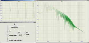
The attached image shows an LTSpice simulation of a diode rectifier. The top left image shows the spiky diode current, the right image is the harmonic spectrum (extending well beyond 10 kHz, i.e. through the entire audio band and beyond), and the bottom-left pane shows the very simple schematic diagram.
The diode used in the simulation is a fast-recovery rectifier diode rated for 1 A. I used this one because it's built into LTSpice, but results will be similar for any other rectifier diode. Fast rectifiers are popular with audiophiles, and make the problem even worse than the old (slower) standbys like the 1N4001 and family.
-Gnobuddy
Attachments
The onboard power supply is quite good. It is a discrete CCS/Shunt regulator which has a good power supply isolation. It draws a constant current in the order of 50mA to 70 mA (depending on the type of LEDs used in the power supply CCS circuit). To reduce the high current spikes small resistors can be put in series with the AC inputs of the board.The onboard power supply is perfectly fine and very quiet. I replaced the IC with LME49720, but the NE5532 works fine too. It is a very good, inexpensive way to play with Linkwitz-Riley crossover.
One thing missing is the level (volume) control for individual bands.
....The current through a rectifier diode.... consists of sharp, short pulses. ....good practice to keep wires from transformer to rectifier diodes, and between rectifier diodes and filter caps, as short as possible to minimize radiation of this noise. .. This board violates that rule....
Good advice; and yes violation is not always punished. (Aside from "short", we should have "minimum loop area".)
Several things here. While the layout is not "The Best", it is still fairly small. Also the "high" current spikes are limited by the high resistance of small transformers (and greatly over-sizing, like 50VA for a 2VA load, may not be the best policy). And the (unusual) regulation may be quite good; IF the ground path routing does not contaminate regulator with cap-spikes.
I've built stuff this small and got away with it. Skill? Luck?
We could wish the layout didn't have the one cap SO close to the filter amps. I've proposed a hierarchical layout; possibly the actual layout is a paste-up of existing bits+pieces and not obsessively optimized (the market does not demand it). I'd "like" to see the transformer wires shorter and even twisted but at least they have been routed away from the audio-stuff.
Attachments
....traditionally in a module called "PROBE". Which originally printed ASCII characters on greenbar paper. The input to SPICE was originally punched-cards, and remnants of that technology can still be found in the internal workings. Also it comes from an era when not all terminals had lower-case characters. When FORTRAN was the only good way to work formulas.
Found a Philips SPICE-alike article. You draw the circuit by hand. You number the nodes. You punch cards (by this time, a text file) expressing the circuit as node numbers and part values. A .TRAN run would output to a "line" (text-only) printer, often on pinfeed greenbar paper. I do not know why time is on the left and voltage runs sideways. And it does look like this line-printer has a fine dot capability-- 5+ years later I was plotting "*" without microspace, so it was real chunky.
Attachments
that's why we still call it a spice deck (of cards).
the maximum number of characters was limited to 80,so the + signwas used as a continuation of the previous line.
re toroids.the smaller ones are quite sensitive to DC. I lost a few due to an intermittent contact creating net DC,saturating the transformer and burning the primary. fusesare too big to protect the small currents..
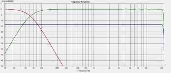
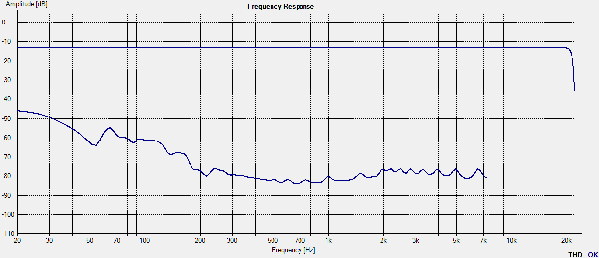
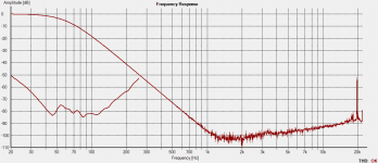
Hey remember me? Long time no see. I 've had the LR crossover delivered for a while now, but only got the chance to tinker with it now. Here's a frequency response graph from HOLMImpulse, for your viewing pleasure. The crossover point I requested was 60Hz.
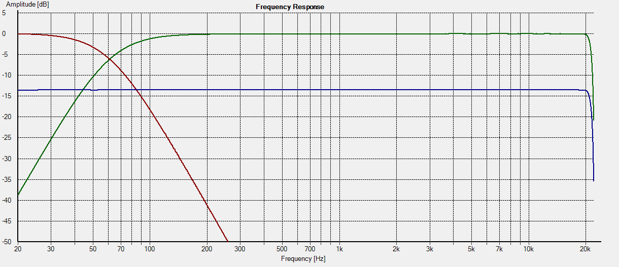
Blue line is my audio interface recording itself with a loopback, as a baseline indication. Besides the frequency splitting, the crossover offers 13.6dB of gain which is pretty welcome. I think I 've come across this gain value in the past so I am assuming it's directly related to and a specific result of using the NE5532 opamps.
Actual crossover frequencies are 61Hz for the left channel and 62Hz for the right, so they got it right. I asked them to not go under 60Hz so they made sure the components satisfied that requirement. Just for fun, I 'll be measuring the capacitor values because I think that's where the small discrepancy between left and right channel comes from.
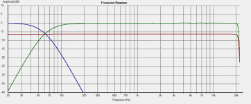
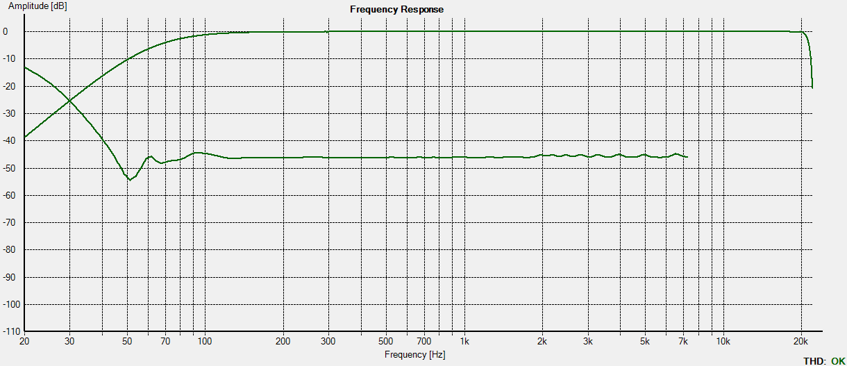
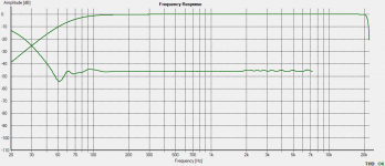
Just for fun, I hooked up a 10K resistor to each of the low pass and high pass outputs, connected the resistors, and measured the summed output:
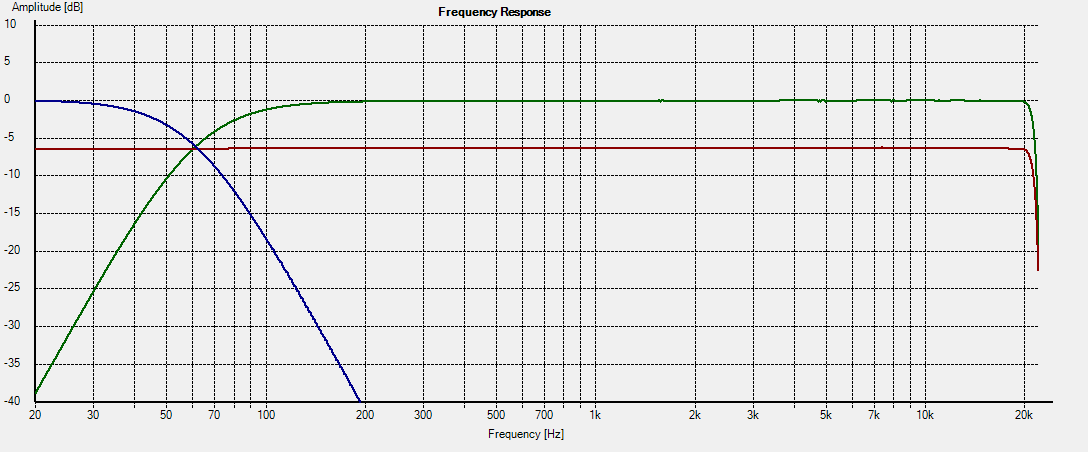
As expected, the frequency response of the summed output is pretty much flat. Gain loss of 6-7dB is due to the resistors of course.
What can I say, it works. 🙂
Blue line is my audio interface recording itself with a loopback, as a baseline indication. Besides the frequency splitting, the crossover offers 13.6dB of gain which is pretty welcome. I think I 've come across this gain value in the past so I am assuming it's directly related to and a specific result of using the NE5532 opamps.
Actual crossover frequencies are 61Hz for the left channel and 62Hz for the right, so they got it right. I asked them to not go under 60Hz so they made sure the components satisfied that requirement. Just for fun, I 'll be measuring the capacitor values because I think that's where the small discrepancy between left and right channel comes from.
Just for fun, I hooked up a 10K resistor to each of the low pass and high pass outputs, connected the resistors, and measured the summed output:
As expected, the frequency response of the summed output is pretty much flat. Gain loss of 6-7dB is due to the resistors of course.
What can I say, it works. 🙂
Attachments
Hello again,
I discovered this nice checkbox on HOLMImpulse's interface labeled "Distortion". I picked THD and these are the results for loopback, lowpass, highpass:
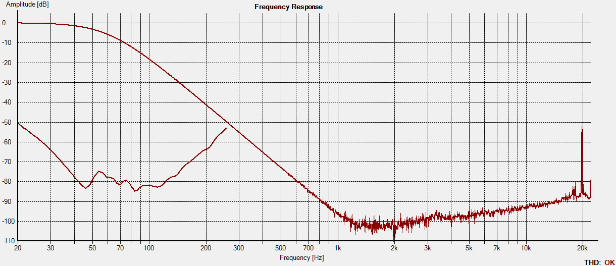
Could someone explain what these additional lines indicate? They look quite irregular which makes me wonder. Especially the loopback curve.
I discovered this nice checkbox on HOLMImpulse's interface labeled "Distortion". I picked THD and these are the results for loopback, lowpass, highpass:
Could someone explain what these additional lines indicate? They look quite irregular which makes me wonder. Especially the loopback curve.
Attachments
The NE5532 is a very nice op-amp that can be configured for any voltage gain from a rather useless zero (in inverting mode) up to x100,000 (i.e. +100 dB), its open-loop gain at DC and very low frequencies....13.6dB of gain...I am assuming it's directly related to and a specific result of using the NE5532 opamps.
Perhaps your 13.6 dB is specific to the specific circuit used to achieve the Linkwitz-Riley response. The generic Sallen-Key active filter topology ( Sallen–Key topology - Wikipedia ) has unity gain in the pass band, but sometimes needs awkward values of R and C.
An alternative, very similar-looking topology, keeps the frequency-determining C's equal to each other, but tweaks the voltage gain of the op-amp above unity to achieve the desired frequency response; one gain for a Bessel response, another gain for a Butterworth response, and so on.
It's a lot easier to buy two 10nF 1% caps than to find one 10nF and one 14.7 nF cap, so the equal-cap-value implementation is much more practical in many cases.
Since your Linkwitz-Riley filter is two cascaded second-order Butterworth filters, one possibility is that the gain of each Butterworth stage is half of 13.6 dB, or 6.8 dB. I haven't researched that at the moment (in a rush), but that does seem a wee bit high from memory, particularly for a low-Q Butterworth response.
Another plausible explanation is that multiple Ebay sellers are all selling copies of the same circuit, probably published in Elektor or Wireless World a few decades ago, and the original circuit just happens to have had 13.6 dB of gain. 😀
I wouldn't worry at all about 60 Hz vs 61 Hz corner frequencies - really a meaningless difference in such a low-Q filter type, where the "corner" is very imprecise and extends over quite a range of frequencies. A bit like looking for the edge of the rainbow. 🙂
-Gnobuddy
- Home
- Source & Line
- Analog Line Level
- Help needed: Linkwitz-Riley frequency response curves