If you bought the ldr kit from me, you got it with latest firmware already. If you want to update the firmware to latest follow the link in my signature. Any other option is not an option🙂
Got it, thanks. I was confused by the folder structure in your google drive; especially that all mk I stuff is in the root folder (including the README file) and all mk II stuff is in its own subfolder...
Got it, thanks. I was confused by the folder structure in your google drive; especially that all mk I stuff is in the root folder (including the README file) and all mk II stuff is in its own subfolder...
Thanks for letting me know, I will reorganize it in a more logical manner.
Another display that works with this project, requires no additional components to be soldered and cheapest I could find:
White 2.42" 2.42 inch LCD Screen 12864 OLED Display Module IIC I2C SPI Serial for C51 STM32 SSD1309-in Integrated Circuits from Electronic Components & Supplies on Aliexpress.com | Alibaba Group
I've got this display and apparently it can be configured for IIC or SPI. The picture of the back side in the link to alibaba shows the version configured for IIC (R8 empty; R9-12 are under the yellow ribbon cable).
I got the version configured for SPI (R8 present; R9-12 empty). I guess I have to remove R8 and short the solder pads of R9-12. But are SCK of the OLED the same as SCL of the LDR Pre ("Serial ClocK" vs "Serial CLock")?
It's the same signal, unless you see something else on the display that is a closer match 🙂
Hi Zdr,
I spent some time fault finding the screen which was glitching and I found there was a very tiny hairline crack in the pcb track near the SDA connection.
after soldering this it has been working flawlessly.
I also found holding the DC pin low worked for me (this may be obvious)
But i did not know until I read the datasheet (RTFM issue)
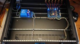
I just thought I would mention this if anyone else has trouble, wiring is per attached picture, DC pin connected to earth. I have not had one screen glitch since. Very happy with this design and the sound, credit to Neb.
(using the latest version Zdr power supply with 4 x LM7805)
-Dan
I spent some time fault finding the screen which was glitching and I found there was a very tiny hairline crack in the pcb track near the SDA connection.
after soldering this it has been working flawlessly.
I also found holding the DC pin low worked for me (this may be obvious)
But i did not know until I read the datasheet (RTFM issue)
I just thought I would mention this if anyone else has trouble, wiring is per attached picture, DC pin connected to earth. I have not had one screen glitch since. Very happy with this design and the sound, credit to Neb.
(using the latest version Zdr power supply with 4 x LM7805)
-Dan
Attachments

Hi Zdr,
I spent some time fault finding the screen which was glitching and I found there was a very tiny hairline crack in the pcb track near the SDA connection.
after soldering this it has been working flawlessly.
I also found holding the DC pin low worked for me (this may be obvious)
But i did not know until I read the datasheet (RTFM issue)
I just thought I would mention this if anyone else has trouble, wiring is per attached picture, DC pin connected to earth. I have not had one screen glitch since. Very happy with this design and the sound, credit to Neb.
(using the latest version Zdr power supply with 4 x LM7805)
-Dan
Dan, thanks for sharing - nice catch🙂
New FW
New firmware posted, no big changes. Removed remote bug (LDR was reacting to repeat press from other remotes) from "C" version (for character OLED), and added back A/B switching to the center button to both versions (C and G).
Center button functions:
1. short press: switches between two last inputs for A/B comparisons
2. long press, same as before: enters setup menu.
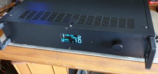
This is another type of oled that works well, no need to add any parts. You do need to remove flat cable on the back to put solder blobs. Do not forget to pull the gray plastic before sliding out flat cable.

Last edited:
Hi ZDR, I'am testing my LDR Pre MKII at the moment. When I start-up the following message shows up:
Error 21: LSE Power Failure
The measured the LDR resisitance of LSE is 85 ohms. I can also set the BIAS to 700K without a problem. The three relays are activated (on).
Pleas advice, what could cause this error?
Error 21: LSE Power Failure
The measured the LDR resisitance of LSE is 85 ohms. I can also set the BIAS to 700K without a problem. The three relays are activated (on).
Pleas advice, what could cause this error?
Thanks for the directions, I found a bad solder joint at one of the relais. The unit is calibrated and 100% functional. Now it is time to test
just to let you know, the LDR project works great. I'am very satisfied with the sound and functionality.
One question though, how can I add on/off functionality? Somewhere I have read that a second encoder could be used. Could someone explain how this works?
One question though, how can I add on/off functionality? Somewhere I have read that a second encoder could be used. Could someone explain how this works?
just to let you know, the LDR project works great. I'am very satisfied with the sound and functionality.
One question though, how can I add on/off functionality? Somewhere I have read that a second encoder could be used. Could someone explain how this works?
Yes, second encoder can be used. You also have standby function (on/off) on the remote, invoked when you press and hold play button.
There is no connector for second encoder on board, so you need to solder wires directly to arduino in order to connect it:
pin 13 - to encoder button
pin 11 - to encoder CCW
pin 12 - to encoder CW
gnd - to encoder gnd
Ned,
A little over a year ago I built out two of your MkII LDR Preamp PCBs, from your first production run. I ran them through configuration and placed them into storage awaiting the completion of my DCG3 and B1with Kong Triode projects.
After completing the DCG3, I transferred it into a case and wired in the LDR MKII for volume and switching. On startup, the Mk II brought up the flash screen and it went into standby (three dots on the lower right side of the screen); however, nothing I did with the encoder or remote would bring it out of the standby mode. I checked and rechecked the encoder wiring, changed encoders and even shorted between the VCC and ground pins on the board. To ensure that it was a system problem, I wired up the second board and found the same results.
What is so strange about this problem is that both boards had been run through configuration prior to being placed in storage. I assume that they had the initial version of your firmware, and as I saw that you had mentioned a problem with coming out of configuration in the fixes included in a firmware version that you posted, I decided to reflash them with the latest version of the firmware for a single encoder (v1.17).
Following the relatively brief information from your “readme” file. I created a firmware subdirectory off my “C:” drive and downloaded the listed files. As in the “readme”, running the “burn” batch file with no extensions brought up the documented message; however, running the burn file with the appropriate arguments for com port and hex file brought up the following avrdude error message. “The code execution cannot proceed because libusbo.dll was not found. Reinstalling the program may fix the problem.
Given the error message, I downloaded another version of avrdude from your directory. Unfortunately, rerunning the batch file resulted in the same error message. Any idea why I could not bring the two boards out of standby and/or what the error message from attempting to install a new version of your firmware is about?
Regards,
Roy
Neb,
Found that out during my debugging process. I would recommend that you provide more information about what the "avrdude" distribution consists of and consider including "libusbo.dll" with the rest of your firmware distribution since it will not run without it. As an avrdude distribution is included with the Arduino IDE and I had installed it while working with version I of your LDR board I had the solution available. I searched for "avrdude.exe" on my computer found it in the xloader subdirectory along with the required "libusbo.dll". Placing Burn.cmd and the .hex file of choice in the xloader subdirectory allowed the firmware update to operate correctly.
Regards,
Roy
Sorry, I did not have this issue so was not aware of it. Each environment is different and difficult to predict. Apparently avrdude is difficult to run standalone, and other apps have their share of problems too. If you can recommend a portable app that can easily run on every pc and burn firmware, I would be more than happy to try it. I could not find it myself.
- Home
- Source & Line
- Analog Line Level
- LDR Pre MkII - LDR volume control and I/O switching