Excellent thread here!
Learning a lot on the trade offs between various topologies.
I’ll be following this closely.
PS even though the clicking is common in r2r ladders I believe it can be mitigated via software and/or other tricks.
Despite this drawback I’ve used this design in my system for some time and have come to view the clicking as gratifying.
Last edited:
My goal was to build as much a drop-in line stage, complete with input and output circuitry, as a volume controller. <snip>
* Inductive Volume Controls
- Autoformer
- Transformer
[*]Stepped attenuators (e.g. goldpoint) - I heard these can be motorized, too, but I've never come across one.
Khozmo used to do one before their current model (which is now relay based with an optical encoder to control). And Bent Audio do an add-on kit for a few.
Last edited:
Seems like many people are coming up with different ideas for the volume control.
I did also, more conventional, digitally controlled volume, input, mute and IR remote.
See
 Home > Forums > Source & Line > Analog Line Level
  Preamp Control -Volume,input,mute, remote Have a good one.
John
I did also, more conventional, digitally controlled volume, input, mute and IR remote.
See
Home > Forums > Source & Line > Analog Line Level Preamp Control -Volume,input,mute, remote Have a good one. John
Controlling the volume control chips
I got a request to share the Arduino sketch I used to control the MUSES72320 chip. In response, I attach the sketches to control each of the three digitally controlled boards I developed.
The sketches were created for test purposes, so they are functional but very much barebone. Let me know if you spot an error in any of the sketches.
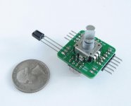
As a little preview, I am finalizing a "digital knob" - see the picture. It is an Arduino in a very small form factor with an encoder attached and UART, SPI, I2C and some GPIO pins exposed. It can control any of the boards described above, plus one new board to be published soon. The encoder is a 12mm incremental encoder from ALPS (EC12), Bourns (PEC11R), or similar.
I got a request to share the Arduino sketch I used to control the MUSES72320 chip. In response, I attach the sketches to control each of the three digitally controlled boards I developed.
The sketches were created for test purposes, so they are functional but very much barebone. Let me know if you spot an error in any of the sketches.
As a little preview, I am finalizing a "digital knob" - see the picture. It is an Arduino in a very small form factor with an encoder attached and UART, SPI, I2C and some GPIO pins exposed. It can control any of the boards described above, plus one new board to be published soon. The encoder is a 12mm incremental encoder from ALPS (EC12), Bourns (PEC11R), or similar.
Attachments
Now with the DS1882
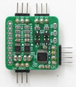
As announced in my last post, here is one more volume controller. This one is based on the DS1882 digital pot, with the output buffered by matched JFETs, B1/Mezmerize style. The digital potentiometer, two JFET buffers and their analog power supply regulators are mounted on one 1100x1100mil (28x28mm) board.
As announced in my last post, here is one more volume controller. This one is based on the DS1882 digital pot, with the output buffered by matched JFETs, B1/Mezmerize style. The digital potentiometer, two JFET buffers and their analog power supply regulators are mounted on one 1100x1100mil (28x28mm) board.
Attachments

A very nice project. It can be seen that the EMU 0204 has big problems with the distortion at higher frequencies.
Very interesting project. Do you sell boards and/or would provide gerber/kicad files?
Thank you! The boards will be available for sale shortly.
A very nice project. It can be seen that the EMU 0204 has big problems with the distortion at higher frequencies.
Thank you!
Indeed, even though EMU0204 is a good and capable sound card, it is not quite up to the task of measuring the HF distortion of a low distortion line stage. I wouldn't call it big problems though - it is just that this line stage performs very well.
do you have boards for the PGA2310? i need 6 channel balanced for my active crossover. thank you
As announced in my last post, here is one more volume controller. This one is based on the DS1882 digital pot, with the output buffered by matched JFETs, B1/Mezmerize style. The digital potentiometer, two JFET buffers and their analog power supply regulators are mounted on one 1100x1100mil (28x28mm) board.
Hey Alex,
What’s the difference, if any, between your digital pot approach and a MDAC attenuator?
Thank you
Hey Alex,
What’s the difference, if any, between your digital pot approach and a MDAC attenuator?
Thank you
I think the main difference is resolution, in theory is easier to find DACs w/ higher resolution than digital pots. But I may be wrong.
Yes, I have the boards for all of the above volume controls. Just sent you a PM.do you have boards for the PGA2310? i need 6 channel balanced for my active crossover. thank you
What’s the difference, if any, between your digital pot approach and a MDAC attenuator?
You want a log relationship between the control code and the output level in a volume control, and a digital pot does just that. MDACs, on the other hand, generally have a linear relationship between the control code and the output level. While the number of steps may be higher (e.g. 256 in a 8-bit DAC vs. 64 in the DS1882), in terms of perceived volume these steps are more coarse at the low end, where you want them fine, and fine at the high end, where you don't need that. One can try to correct that in software, but it would reduce the effective resolution and increase complexity. There was an interesting chip, the AD7112 (see the attached datasheet), now obsolete, that did it in hardware.I think the main difference is resolution, in theory is easier to find DACs w/ higher resolution than digital pots. But I may be wrong.
Other than the resolution, the working principle of a digital pot (an R-string DAC) is different from that of an MDAC (that usually employs an R-2R ladder). You need to look at how an MDAC, a digital pot, a mechanical pot or any other control fits into your schematic. For example, a digital pot may be sensitive to loading - the reason I included a JFET buffer in the schematic above. For another example, a typical current output MDAC relies on an I/V converter, usually an opamp (again, see the attached datasheet for an example).
Attachments
Last edited:
I believe the MAS6116 is the same thing as the WM8816, which I did use in one of my boards.There is another excellent digital pot MAS6116. Have you tried it?
OK I get it. I wish the AD7112 was still in market, I would've preferred to control the steps via software (custom curve through lookup table, for instance).You want a log relationship between the control code and the output level in a volume control, and a digital pot does just that. MDACs, on the other hand, generally have a linear relationship between the control code and the output level. While the number of steps may be higher (e.g. 256 in a 8-bit DAC vs. 64 in the DS1882), in terms of perceived volume these steps are more coarse at the low end, where you want them fine, and fine at the high end, where you don't need that. One can try to correct that in software, but it would reduce the effective resolution and increase complexity. There was an interesting chip, the AD7112 (see the attached datasheet), now obsolete, that did it in hardware.
In any case, seems like these digital pots have a very nice resolution. If I'm not mistaken, you can get 0.5dB steps on the WM8816, MUSES72320 and PGA2310, or 1/2/3 dB steps (depending on the position) for the DS1882.
Other than the resolution, the working principle of a digital pot (an R-string DAC) is different from that of an MDAC (that usually employs an R-2R ladder). You need to look at how an MDAC, a digital pot, a mechanical pot or any other control fits into your schematic. For example, a digital pot may be sensitive to loading - the reason I included a JFET buffer in the schematic above. For another example, a typical current output MDAC relies on an I/V converter, usually an opamp (again, see the attached datasheet for an example).
Still very interested in your approach. I'm reading through the datasheets. WM8816 for instance. Sorry again for the newbie following questions.
1. I'm assuming the microcontroller (Arduino, RPi...) knows at every moment not only the position of the encoder, which is sent to the pot, but also the attenuation generated by the pot (ie volume in dB), is that the case? I mean, I want to be able to show the real dB volume in the display.
2. Not really sure at all what the ±18V input signal refers to.
3. Gain range from -111.5dB to +15.5dB. Am I understanding correctly that we can attenuate the original DAC output but also have gain? (ie like attenuating from positions 0-128 and gain from 129-256, or whatever)
4. How is the output VRMS and Zout calculated?
Thank you so much again
The datasheet for WM8816 (or any other volume control chip) defines the relationship between the gain/attenuation in dB and the code that you send to the chip. Your MCU can get the input from e.g. an encoder, display the dB number, calculate the appropriate code and send it to the volume control.1. I'm assuming the microcontroller (Arduino, RPi...) knows at every moment not only the position of the encoder, which is sent to the pot, but also the attenuation generated by the pot (ie volume in dB), is that the case? I mean, I want to be able to show the real dB volume in the display.
WM8816 is unusual in that it handles +/- 18v input with only +5v power supply. Other chips, e.g. PGA2310 or DS1882, need analog supplies, and the input signal cannot exceed those analog supplies.2. Not really sure at all what the ±18V input signal refers to.
WM8816 has not one but two digital pots for each channel. These pots work together with an external opamp to provide gain or attenuation.3. Gain range from -111.5dB to +15.5dB. Am I understanding correctly that we can attenuate the original DAC output but also have gain? (ie like attenuating from positions 0-128 and gain from 129-256, or whatever)
Output Vrms = input Vrms * 20 * log10(dB gain). There are plenty of online calculators to do the math for you, for example, this.4. How is the output VRMS and Zout calculated?
Zout and current drive capability will depend on the opamp you use.
hey happy new year!
Another question knocking my head, and sorry if it sounds very stupid question. I suppose the internal opamps do transform the audio signal (signal and noise) not only attenuate/amplify(gain) by changing the Vref, right? Where I'm going is, do these digital pots "have a sound"?
thank you again!
Ah OK, what I need then.The datasheet for WM8816 (or any other volume control chip) defines the relationship between the gain/attenuation in dB and the code that you send to the chip. Your MCU can get the input from e.g. an encoder, display the dB number, calculate the appropriate code and send it to the volume control.
I think it's cleaner if we use two power sources, one for digital and one for analog. Also, at least in PGA datasheets, they also recommend to have D/A ground planes separated, and they even place the pins favoring that design, which is cool.WM8816 is unusual in that it handles +/- 18v input with only +5v power supply. Other chips, e.g. PGA2310 or DS1882, need analog supplies, and the input signal cannot exceed those analog supplies.
Yes. I probably did not expose the question properly, excuse my english. What I want to know is, for instance, if I have a DAC outputting 1.2V RMS, I assume at minimum volume that will be 0V, at some point, it will be no attenuation so 1.2V, and from some point we get some gain, idk how much but let's imagine 2V?WM8816 has not one but two digital pots for each channel. These pots work together with an external opamp to provide gain or attenuation.
Noted.Output Vrms = input Vrms * 20 * log10(dB gain). There are plenty of online calculators to do the math for you, for example, this.
Zout and current drive capability will depend on the opamp you use.
Another question knocking my head, and sorry if it sounds very stupid question. I suppose the internal opamps do transform the audio signal (signal and noise) not only attenuate/amplify(gain) by changing the Vref, right? Where I'm going is, do these digital pots "have a sound"?
thank you again!
- Home
- Source & Line
- Analog Line Level
- Balanced Volume Controller / Line Stage