First of all let me thank you for your support.
I understood that my first error was the missing net-tie. It was because diptrace doesn't support it... so I skipped it.
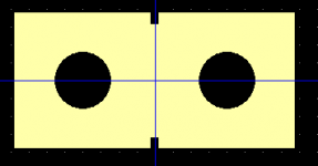
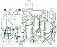
I read a lot about net-tie and how to do it and I created attached one.
It is composed by 2 pass-through pads and one connection on the top layer. Probably I can increase the distance between 2 pad, but I will check after.
I tried to put all net-tie "at the same place" of your PCB.
Is this result acceptable?
I understood that my first error was the missing net-tie. It was because diptrace doesn't support it... so I skipped it.
I read a lot about net-tie and how to do it and I created attached one.
It is composed by 2 pass-through pads and one connection on the top layer. Probably I can increase the distance between 2 pad, but I will check after.
I tried to put all net-tie "at the same place" of your PCB.
Is this result acceptable?
Attachments
The only reason I suggested you (re-)read the article is that I don't think I can explain its ideas any better. So I just quote:
The node that was originally tied to the ambiguous node called “ground” no longer needs to be connected anywhere unless required to keep the op amp input from overloading with common-mode signals. In that case the sensible place is on the ground plane near the op amp’s decoupling caps, as this is implicitly the HF reference of the op amp. Ideally the feedthrough from this point to the differential output voltage is zero, which is why we have that liberty.
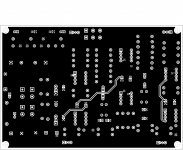
A salient feature of the board layout is that all components are placed in pairs. [...] [W]e’re trying to make sure that any interference affects both legs equally. Another way of putting this is that the area enclosed by a differential pair must be as small as possible.
I have been using Eagle CAD (now owned by Autodesk) and a number of PCB manufacturers worldwide. The one EU based PCB house I dealt with is EuroCircuits. In SE Asia, the easiest one is probably Seeed Fusion.
I did not experience transients at the output, so I did not include the relay.
Ok, clear.
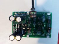
In any case I closed the PCB yesterday and ordered it.
I added pin for +/-15V and GND so if I will need something else I will take the power from there.
The shipment will be slow (25 days) so I will post some photo and impressions soon later.
The shipment will be slow (25 days) so I will post some photo and impressions soon later.
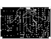
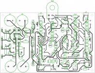
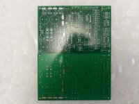
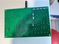
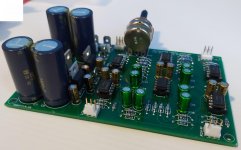
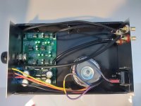
So boards arrived (see attached photo).
I assembled everything but unfortunately I have a big issue.
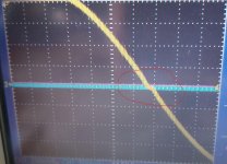
In the scope image you can see a distortion near the zero value... I can hear it when the music is playing.
It seems that it compare soon after the first stage. I don't understant what is wrong because the schema and connection seems ok.
Do you have any idea to investigate/solve the problem?
Attachments
I have a power amp that I'd like to be able to switch between single-ended RCA and balanced XLR inputs. The internal amp circuitry looks to be ground referencing..
Using one of these boards as an interface, would I be better off placing the switch before the board (using Putzeys method of interfacing single-ended to his BPBBP) or would it better switching between this board (for XLR) and a direct RCA input?
Will the board be perhaps best for both inputs as a kind of buffer ?
EDIT: I should have looked at your website first! It answers my question:
- Balanced differential input with excellent common mode rejection - works very well with single ended sources, too!
Last edited:
would I be better off placing the switch before the board (using Putzeys method of interfacing single-ended to his BPBBP) or would it better switching between this board (for XLR) and a direct RCA input?
You can probably get good results both ways. My preference would be to use the balanced input for both balanced and single ended sources, and preferably use ground sensing for the local-ground-references power amplifier. This way, you would have much less to worry about in terms of ground loops, cable influence and other issues associated with SE-to-SE connection. On the other hand, if the power amp handles SE sources well by itself, there should be little downside keeping it in that role.
Can’t think of what could be the issue with you board, or perhaps with the signal source. Try isolating the problem. Go stage by stage with the scope and see what is going on where in terms of both DC and AC.In the scope image you can see a distortion near the zero value
Crossover distortion is a result of bad biased transistors. How can it be with op amps? I think you have a DC bias problem due to missing caps in the signal path or wrong resistors.
yes, I thought so... but in practice I didn't find any problem.
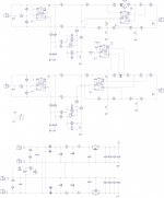
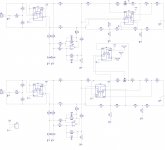
the input signal is the output of a DAC (pcm5102A). The input sine with the oscilloscope is good. If I connect the dac directly to the ampli I can here the 1kHz beep ok, with the preampli I can here a "prrrr" in background.
For semplicity I attached the schema.
I also supposed to some fried capacitor (bypolar??) but my doubt is that the issue is present on both channels... so this means that I have more components fried...
Can be something related to net-ties? How can I check?
But the very strange thing is that the problem is soon after the input stage. If I put the probe on the output of U3A and U3B I can see the distortion.

Attachments
Is it the same in both channels?
What do you see at the input of U3A/B when it is connected to your sine source?
Hi Alex
sorry for long delay in my answer but during last week I hadn't the oscilloscope so I can't do measurement.
Today I was able to use an audio card as oscilloscope and I didn't see the problem... so my conclusion should be that my office oscilloscope has some problem? I don't know. Of course it is possible...
In any case I still can hear a "prprpr" when I connect the preampli. But now I noticed that the disturb is present also without input... so it is not a crossover distortion. It is proportional to the voume.
So now my question for you is: do you have any idea about what is this "prprprpr" that I hear?
No, I don'tdo you have any idea about what is this "prprprpr" that I hear?
") It is kinda difficult to debug your board by the seat of one's pants. You need to do some systematic analysis in order to isolate and identify the problem. For example:
It is kinda difficult to debug your board by the seat of one's pants. You need to do some systematic analysis in order to isolate and identify the problem. For example:- Check is the noise is coming from your signal source
- Check if your power amplifier makes the noise by itself
- Compare one channel with the other
- Check your power supply voltage and current
- Check DC and AC voltages, compare if the two channels have close readings in the same points
- Check if the power supply is clean (no noise on power rails)
- Check the circuit with the scope, stage by stage, and see where the problem appears first
- Etc.
Last edited:
- Home
- Source & Line
- Analog Line Level
- Balanced Volume Controller / Line Stage