

The BOM for the pot one states 1/2 & 1/4 resistors but looking at your other balanced line receiver that uses 1/6 resistors then i can safely assume that i can use 1/6 or even 1/8 resistors in the signal path since they are easier to find in smaller sizes.
Those actually are compact metal film resistors in the axial 0204 package (i.e. 2mm diameter, 4mm length). The example part numbers are from Vishay SFR16S series, which is rated for 0.5W (see the datasheet).
Still, sorry about the confusion - I will edit the BOM description for clarity.
Still, sorry about the confusion - I will edit the BOM description for clarity.
No worries. I was asking because on LCSC vishay is never in stock or available and every other resistor that would fit in size and ppm is either 0.25W or 0.16W.
I recently received a EOL notice from Dig-key, on one of the SFR16S parts 4R7, I had in a list, but it was a packaging option EOL, not the SFR16S series being elinimated. I also use MBA0204
LCSC is not very good for specialty passives and even some very general purpose IC's. Hit and miss.
LCSC is not very good for specialty passives and even some very general purpose IC's. Hit and miss.
Last edited:
Except for the four resistors in the power supply (R1 R2 in the DC input filter and R3 R4 in zener biasing), there is no real power dissipation or large currents anywhere in the circuit, so 1/6W resistors such as YAGEO MFR-12 series will work just fine.
The three-pin regulators cascoded by Darlingtons were designed for, and work well with, higher supply rails. They allow powering the board directly from the power amplifier supply. The practical upper limit there is about +/-35V, limited by the power dissipated by the regulators and transistors.
With lower supply rails, there are several way to configure the onboard regulators:
With lower supply rails, there are several way to configure the onboard regulators:
- If the supply rails are within opamp's power supply ratings (e.g. +/-18V max for the LM4562), you can omit both the transistors and the regulators by just shorting the appropriate pads on the board. Obviously you don't need the zeners and their associated resistors in this case. For example, I have one board running like this from an SMPS that has a separate low current +/-15V output.
- You can omit just the transistors and the zeners and keep the three-pin regulators. This works as long as the regulators drop at least 3V input to output.
- You can keep both the regulators and cascodes, choose appropriate zeners and recalculate their resistors.
You want +/-12V on opamps. At the input of the regulators, you'd need +/-15V. On the bases of the Darlingtons, you'd need +/-(15V+2×Vbe) = +/-16.5V or so. Therefore, the minimum appropriate zener voltage would be 16.5V-12V=4.5V. Choose 4.7V as the closest standard value. Now calculate the resistors (R3 R4). If your supply is +/-19V and the bases of the Darlingtons are at +/-(12+4.7)V, each resistor drops 19-(12+4.7)=2.3V. The current through each resistor needs to be sufficient for the zener to operate; 5mA would be ok. Choose R3 and R4 to be 2.3V/5mA = 460ohm. The standard value of 470 ohm will work well.
Wow you even explained how to get there without asking, what a legend. Tried making my own boards but JLC said the tolerances are not good so i'm redoing the board with 0.127mm instead of 0.2mm signal traces.
The boards arrived and they look absolutely gorgeus in matt black. The only thing i'm unsure of is using 1.2K instead of 12K and 22K instead of 220k since i can only buy 100uF bipolar locally.

Board is up and working. The soldering quality is not the best but it works. In the end i managed to get the part values.

Why did you want to clone my board? You could just get one from me, or design something original.
A story about cloning that I like is that of Peter Daniel's Patek amp. He was criticized for copying the original Gaincard amp and decided to come up with an original design - an unusual and cool one.
A story about cloning that I like is that of Peter Daniel's Patek amp. He was criticized for copying the original Gaincard amp and decided to come up with an original design - an unusual and cool one.
I wanted to go that route first but ran into money issues when starting the project last year. I will make my own version later but that needs more learning. No offence but while cloning it i learned a lot of how its working. These boards wont be sold and only for prototyping.Why did you want to clone my board?
Hi Alex,
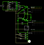
I have a question, I will use your balanced volume controller with PGA2310 volume control as a master buffer (ordered from HIFI Ocean).
But I need to create a unattenuated buffer for record out, can I omit both U5.a and the volume control to realize that from your schematic?
Thanks,
Bas.
I have a question, I will use your balanced volume controller with PGA2310 volume control as a master buffer (ordered from HIFI Ocean).
But I need to create a unattenuated buffer for record out, can I omit both U5.a and the volume control to realize that from your schematic?
Thanks,
Bas.
You'd still need U5A/U8B- they are part of the differential receiver that provides the balanced input functionality. In principle, you can omit the PGA and U5B/U8A (and lose the ground sensing function). If you're using my PCBs, the easiest way is probably to omit just the PGA (shorting pads 9-11 and 14-16 on its footprint) and keep the opamps. It would require no board modifications, and an LM4562 configured for unity gain will be sonically transparent enough.
Thanks for your answer...
If I leave the opamps in as you describe, the signal would be 180 degree out of phase.
Isn't it better then to replace the volume control with another opamp stage to get the signal in phase again?
If I leave the opamps in as you describe, the signal would be 180 degree out of phase.
Isn't it better then to replace the volume control with another opamp stage to get the signal in phase again?
The PGA23xx is non-inverting, so the phase will not change if you omit it. BTW if you want to invert the phase, you can simply swap hot and cold inputs.
- Home
- Source & Line
- Analog Line Level
- Balanced Volume Controller / Line Stage