Hi Alex,
as you know i'm building your MUSES72320 board. I'm using Nichichon caps and Vishay CMF50 resistors.
i have a question about the last stage, i think you kind of answered it already 4 posts above, but i do not yet have the knowledge to be sure.
if i'm not using ground sense, can i bypass the last stage? like this:

since those resistors are close by on the board, i would just put the output resistors (R25, R25) across the pads from R20 to R25, leaving out the unused ones.
I went through the datasheet of the OPA2134, and i see this Opamp can perfectly drive anything from 600 Ohms, just like the LM4562.
i'm also planning not to use the caps which are directly in the signal line, C26 and C27. I saw someone mentioning he was using the MUSES without them just fine.
I see them described in the MUSES72320 datasheet, C26 is basically a highpass (DC block), but is U4.B on your board not already subtracting DC from the signal? i thought that was the entire purpose of that stage, and if i'm right that would make C26 kind of redundant.
C27 seems to provide a low frequency cutoff in U6.B's feedback loop. From what i understood from here, the feedback loop should have a cut-off lower than the input cut-off to prevent DC over the feedback capacitor. I figure that means if i ditch the input cutoff, i should ditch the feedback cutoff too...
Erwin
as you know i'm building your MUSES72320 board. I'm using Nichichon caps and Vishay CMF50 resistors.
i have a question about the last stage, i think you kind of answered it already 4 posts above, but i do not yet have the knowledge to be sure.
if i'm not using ground sense, can i bypass the last stage? like this:
since those resistors are close by on the board, i would just put the output resistors (R25, R25) across the pads from R20 to R25, leaving out the unused ones.
I went through the datasheet of the OPA2134, and i see this Opamp can perfectly drive anything from 600 Ohms, just like the LM4562.
i'm also planning not to use the caps which are directly in the signal line, C26 and C27. I saw someone mentioning he was using the MUSES without them just fine.
I see them described in the MUSES72320 datasheet, C26 is basically a highpass (DC block), but is U4.B on your board not already subtracting DC from the signal? i thought that was the entire purpose of that stage, and if i'm right that would make C26 kind of redundant.
C27 seems to provide a low frequency cutoff in U6.B's feedback loop. From what i understood from here, the feedback loop should have a cut-off lower than the input cut-off to prevent DC over the feedback capacitor. I figure that means if i ditch the input cutoff, i should ditch the feedback cutoff too...
Erwin
LIG and LOG should be LI Shield and LO Shield.
They attach to the metal chassis at their connector.
They are not part of the audio circuit common (Ground).
But there should be a single point attachment of the circuit common to the chassis near the input connector.
They attach to the metal chassis at their connector.
They are not part of the audio circuit common (Ground).
But there should be a single point attachment of the circuit common to the chassis near the input connector.
Hi Speedskater,
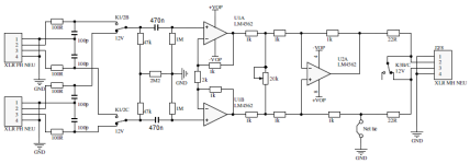
The diagram only shows the local ground of the board itself. Like you say, the shield of the cabling will be directly tied to the chassis at the in and output connectors. I'll try the 16MHz lowpass RC at the inputs too, (100R and 100pF) like in Putzey's original design. Good idea to only connect board ground at the input side to chassis.
The diagram only shows the local ground of the board itself. Like you say, the shield of the cabling will be directly tied to the chassis at the in and output connectors. I'll try the 16MHz lowpass RC at the inputs too, (100R and 100pF) like in Putzey's original design. Good idea to only connect board ground at the input side to chassis.
Yes you can. You will end up with a balanced output (in the sense of equal hot and cold output impedances, not in the sense of two opposite-phase single ended outputs). For best results, you’d want to have a downstream device (e.g. your power amp) with a balanced input. Also, the output phase will be inverted, so you may want to swap the hot and cold input wires.can i bypass the last stage
The big 'lytic caps are as per the MUSES data sheet, intended to block DC current through the internal circuitry. Nichicon ES series works well for me in that role. I haven seen people omitting (shorting) them, but have not tested that myself.
You have seen enough AES publications to know that the reality is a tad more complex.They are not part of the audio circuit
Last edited:
Great. When for some reason i want convert it to single ended, it involves soldering anyway, so i figured might as well go the leanest route. I had not thought about the phase, thanks for pointing it out!Yes you can. You will end up with a balanced output (in the sense of equal hot and cold output impedances, not in the sense of two opposite-phase single ended outputs). For best results, you’d want to have a downstream device (e.g. your power amp) with a balanced input. Also, the output phase will be inverted, so you may want to swap the hot and cold input wires.
I have read that part, but it doesn't say anything about whether the MUSES chip itself doesn't like DC, or that they just advise it as a means of preventing DC at the output, like an application example. The worst source i have has 3mV on an output, i'll do some measuring when it's done.to block DC current through the internal circuitry
To be honest, i only have experience with 1 signal handling capacitor in my entire system. Not a Nichicon Muse or any fancy one, but it was the feedback loop capacitor in my gainclone amps, removing it made such a big improvement, that i will consider every one i will put back in the chain...Nichicon ES series works well for me in that role
Last edited:
This dutch version had me highly intrigued as it seemingly has a better volume (balanced?) solution and it got rid of the complex DC subtraction circuit that is practically never needed in reality. Therefor only 3 opamps per channel. Hopefully it is equal or better than the original design by Bruno Putzeys as the original had a tremendous Achilles heel regarding the volume control.
Pretty much a KISS version with elegance. No display, no electronic volume control, no volume control in the feedback loop, no remote so everyday sports. Much to like or?
Pretty much a KISS version with elegance. No display, no electronic volume control, no volume control in the feedback loop, no remote so everyday sports. Much to like or?
Attachments
Last edited:

I think that version has not much to do with Bruno Putzeys design anymore. If you ask me it just looks like a pot with low output impedance and nothing more. Might i suggest to read his article "The G Word, or How to Get Your Audio off the Ground"his dutch version had me highly intrigued as it seemingly has a better volume (balanced?) solution
Of course I know the article and I can spell it backwards. It IS the Putzeys design but in a version. Despite the talent of Putzeys his volume control was problematic in reality. That is why versions and plug in volume boards were created. Not many were of the same quality or they lacked essential features the original had like onboard regulators, just 1 input and muting (that eventually always seems to be necessary after all). Some have terrible modular construction with mainboard, input board, output board, display board and PSU board where the original had beautiful monolith design (true craftsmanship). Some have the DC subtraction circuit AND input coupling caps 🙂 Some have the relevant input filter omitted....making the original still the best but with the handicap.
I did not ask you and it also is not just a potentiometer with low output impedance. Someone had brain gymnastics and shared this.
I did not ask you and it also is not just a potentiometer with low output impedance. Someone had brain gymnastics and shared this.
Last edited:
i doubt removing the subtraction circuit and putting caps in the signal is a better solution.
This is what Bruno said about the pot:
"Instead of operating as an attenuator, the potentiometer is used as the sole feedback element in an inverting amplifier."
To me it seems he is explaining that this is the only proper way to do volume control with a simple pot, in a simple way.
in the version you posted, the pot is back to being an attenuator.
Last edited:
Yes he may be proud of that but it was also the single largest failure in the design. Even a terribly annoying error after a while. He thought it to be a cheap and good solution to vary gain with a linear potentiometer circumventing its non-linear properties. How nice this may seem from theoretical point of view he did not take practical reality into account enough that potentiometers are mechanical devices with wipers that wear and tear. A failure like a bad/scratchy contact in the potentiometers wiper (THE usual error in potentiometers) can have pretty nasty side effects.
Last edited:
Luckily we have people like Alex 🙂
But this topic is about Alex his boards, maybe we are drifting a bit off-topic?
But this topic is about Alex his boards, maybe we are drifting a bit off-topic?
It were just suggestions to maybe induce new insights or ideas to builders and readers. Bruno Putzeys designed a terrific device that is very hard to supersede in many ways as all absolutely necessary details have been thought of to cater for many real life scenarios except what was discussed.
No guarantees on that schematics, I am not the designer nor am I able to see all possible drawbacks.
No guarantees on that schematics, I am not the designer nor am I able to see all possible drawbacks.
Last edited:
the only thing i can think of to make the circuit simpler and without the pot, is to remove the DC subtraction circuit, and use caps instead, for those who need DC blocking anyways (which i personally do not really), however possibly hurting SQ though. I suppose i can try the board without the subtraction part too, to see if i can tell any difference in SQ. For volume control maybe a resistor ladder? Either the programmable ones like discussed here or a relais/switch version?
Thank you Jean-Paul for sharing the “Dutch” schematic. My only concern is that this kind of level control changes the differential mode signal but not the common mode one. Since CMRR is defined by four discrete resistors and is not astronomical, the common mode part may be dominant at low volume. This may or may not be a practical problem.
As for Putzey’s MicroPre aka BPPBP, is was but a demo project illustrating his article. As such, I believe it has been wildly successful, as so many people learned a thing or two from it. IMO this may be even valuable than a flawless design.
As for Putzey’s MicroPre aka BPPBP, is was but a demo project illustrating his article. As such, I believe it has been wildly successful, as so many people learned a thing or two from it. IMO this may be even valuable than a flawless design.
Yes agreed but without the volume practical problem it would have been pretty close to perfect.
BTW you can ditch the DC subtraction circuit without penalty and substitute for just 2 input caps (or check sources and omit the DC subtraction circuit and use no caps 🙂).
BTW you can ditch the DC subtraction circuit without penalty and substitute for just 2 input caps (or check sources and omit the DC subtraction circuit and use no caps 🙂).
Last edited:
The DC subtractor it is important because of that 2.2 Meg resistor at the input and the opamps input current flowing through it with the input disconnected.
It was meant to solve DC offset voltage of sources in a slight designer/engineering frenzy to add something unusual instead of the usual DC servo. Now I thought DC offset to be a terrible reality until I checked my balanced sources for DC offset.
So it removes DC offset voltage from the inputs which implies it doesn't correct its own possible DC offset at the outputs. Debatable!
So it removes DC offset voltage from the inputs which implies it doesn't correct its own possible DC offset at the outputs. Debatable!
Last edited:
We are all here because we chase a minimalistic solution, right? Just like you Jean-Paul i want the simplest solution there is, which still fits my demands of course. If i don't need any DC protection, i will try to keep it out.
I do find the discussion very interesting. I still do however have the feeling, Putzey's subtractor could be a better sounding solution then caps. Note i have little to no experience messing around with caps though, so the only thing verify this is try it for myself, and still then it will be subjective, because i'm sure all measures just fine.
One of the reasons i feel this way, i found this discussion on ASR, where this was posted:

Seeing it reported from companies like this, and Bruno avoiding them, and the countless discussions about which caps sound good online, makes me question caps enough to at least pursue avoiding them alltogether. Besides in the passive filtering for the mid's and high's in my system, there are currently none.
Hopefully i can share my findings in a few weeks 🙂
I do find the discussion very interesting. I still do however have the feeling, Putzey's subtractor could be a better sounding solution then caps. Note i have little to no experience messing around with caps though, so the only thing verify this is try it for myself, and still then it will be subjective, because i'm sure all measures just fine.
One of the reasons i feel this way, i found this discussion on ASR, where this was posted:
Seeing it reported from companies like this, and Bruno avoiding them, and the countless discussions about which caps sound good online, makes me question caps enough to at least pursue avoiding them alltogether. Besides in the passive filtering for the mid's and high's in my system, there are currently none.
Hopefully i can share my findings in a few weeks 🙂
- Home
- Source & Line
- Analog Line Level
- Balanced Volume Controller / Line Stage