Where is the best place to implement a relay based mute circuit? right at the input jacks before the summing amps/volume control or after the summing amps/volume control right before the amps(6x)?
Relays (3x dpst) will short the inputs to ground. Kinda worried about shorting the op amps outputs(JRC 2068dd) to ground. Thanks for the help most folks eyes glaze over when speaking electro-lingo.(new word!) and having a community online is awesome🙂
Relays (3x dpst) will short the inputs to ground. Kinda worried about shorting the op amps outputs(JRC 2068dd) to ground. Thanks for the help most folks eyes glaze over when speaking electro-lingo.(new word!) and having a community online is awesome🙂
I would always suggest at the output of the opamp but you must include a low value series resistor from the opamp to the relay. Make sure the feedback network connects before the resistor. Your audio output is taken from the other end of the resistor.
Doing it this way ensures that the opamp can stabilise its DC conditions correctly, and placing the relay at the output ensures silent operation. Muting the inputs probably wouldn't achieve much. Resistor can be as low as 22 ohm or so.
Doing it this way ensures that the opamp can stabilise its DC conditions correctly, and placing the relay at the output ensures silent operation. Muting the inputs probably wouldn't achieve much. Resistor can be as low as 22 ohm or so.
Thanks Mooly! The low value resistor acts as a load for the op amp? looking at Elliot sound circuit they use 100 ohm would you recommend less? So the relay should be shorting the inputs to the power amps?
Not so much a load, more a means of isolating the opamp output from the short to ground that the relay introduces.
Having no resistor would mean that at the instant the relay opens there could be a loud bang as the opamp output would produce a massive spike as it biased up correctly.
A low value resistor is sufficient to allow the feedback network to establish the correct DC conditions. No hard and fast rules on value and a 100 ohm is fine. In practice you might find you could go as low as just a few ohms without problems. Its up to you. If the chip is driving a capacitive load (long cable) then 100 ohms is sensible. If its all internal PCB print of a few cm length then you can go lower.
An empirical approach is good here. 100 ohm will be fine as will 22 ohms. When you reach a value that causes problems, increase it perhaps by four times.
If the chip is driving six amp inputs in parallel then 100 ohm might be a wiser choice.
Why such a low series resistor value? When in mute, the op amp will be driving a screamingly low value, which will surely send the op amp into current limit, dumping hash-like signal related junk into the power supply rails and testing the thermal capabilities of the IC. It seems a lot safer to use some 10kΩ tackdown resistors on either side of an SPST series switch between the amp and the output jack. That way, no DC pops will happen during switching, and the load can always be driven cleanly.
Looks good! No unnecessary loading of the output amplifier, and only one resistor vs. my suggestion for two. The DC 'thump' will happen regardless of any of these muting schemes if the output amplifier has a significant DC fault - that is a problem that needs to be solved outside of the mute circuit. A truly minimal circuit - thanks!
I use a shorting relay on the output with 47 ohm series resistor between op amp and relay. It's all controlled by a humble 555 timer. Turn on delay of about 1.5 seconds, and "instant" off.
It works perfectly - never a pop, click, or thump.
It works perfectly - never a pop, click, or thump.
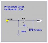
Suggested muting relay
Dear all,
I am modifying my CD player and adding a tube output (lampizator style).
Problem is that when I turn off, the pop is very loud, so I am looking into putting a muting relay before the RCAs.
That would be controlled by the same 5V signal which drives the muting transistors at the output of the stock opamps stage.
Question> which relay do you suggest?
Thanks
Fabrizio
Look for a small signal DPDT type. The quality doesn't really matter because it is only ued to short the audio, not pass it.
You will have to decide what coil voltage is needed as that depends on the rail you intend to run it off. A FET like a 2N7000 or 7001 makes a good interface driver for switching the coil.
You will have to decide what coil voltage is needed as that depends on the rail you intend to run it off. A FET like a 2N7000 or 7001 makes a good interface driver for switching the coil.
Look for a small signal DPDT type. The quality doesn't really matter because it is only ued to short the audio, not pass it.
You will have to decide what coil voltage is needed as that depends on the rail you intend to run it off. A FET like a 2N7000 or 7001 makes a good interface driver for switching the coil.
Thanks Mooly,
I am planning to reuse the muting driver (2SA1015 PNP BJT) as in the picture attached so I hope that will work. It's rated upt to 150mA although the available voltage at the collector would be slightly lower than 5V.
One more question: are you aware of any problem in shorting the audio signal at the output of a tube stage?
Thanks again
Fabrizio
Attachments
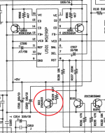
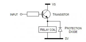
The 2SA1015 is fine as a relay driver (remember to add a damper diode across the coil) and also make sure the transistor saturates when on by checking that there is only a few millivolts across E and C. The 4k7 base resistor could be lowered if needed to get a bit more drive current.
Can't see any issue shorting a valve stage because the output will be AC coupled anyway.
Can't see any issue shorting a valve stage because the output will be AC coupled anyway.
The 2SA1015 is fine as a relay driver (remember to add a damper diode across the coil) and also make sure the transistor saturates when on by checking that there is only a few millivolts across E and C. The 4k7 base resistor could be lowered if needed to get a bit more drive current.
Can't see any issue shorting a valve stage because the output will be AC coupled anyway.
Thanks, what do you mean by damper diode?
Sorry I am not familiar with relays...
When current in a coil is interrupted suddenly, the magnetic field collapses and induces a back emf which needs to be damped to prevent damage.
A diode (such as a 1N4148 for a small relay coil) is placed across the coil so that it is reverse biased.
A diode (such as a 1N4148 for a small relay coil) is placed across the coil so that it is reverse biased.
Attachments
For muting a circuit I prefer to disconnect one circuit from another with the relay and ground the input side of the "next" circuit stage, NOT grounding the output of any circuit, even through a current limiting resistor.
See another thread for schematics and discussion of this: Preamp Control - Volume, input, mute, remote
See another thread for schematics and discussion of this: Preamp Control - Volume, input, mute, remote
For muting a circuit I prefer to disconnect one circuit from another with the relay
and ground the input side of the "next" circuit stage, NOT grounding the output
of any circuit, even through a current limiting resistor.
Shorting the source to ground through a resistor works fine, and keeps the contacts
out of the signal path.
Shorting the source to ground through a resistor works fine, and keeps the contacts
out of the signal path.
Thanks John and Ray for the comments.
Is a series resistor to ground the signal necessary?
The only problem I am trying to solve now is, when I turn off the CD player, to keep the output muted for as long as possible. In fact the voltage spike coming out of the tube stage is around 1s long. So I am adding caps in parallel to the relay coil as well as trying relays with lower activation voltage.
Any experience with that?
- Status
- Not open for further replies.
- Home
- Source & Line
- Analog Line Level
- where to place mute circuit?