when I turn off the CD player, to keep the output muted for as long as possible.
You can to use a timer to control the muting time delay needed.
There are circuits using a 555 timer that can delay up to a minute or more.
You may have large output voltage transients on both turn on and turn off.
Use a normally closed relay (shorting to ground), and the output will be
muted unless enabled by the timer.
For a tube stage, a series resistor isn't necessary when grounding the output.
I would suggest 20-30 seconds for warm up delay for a tube stage, and no delay
for the turn off. A bicolor status LED can show when the circuit is in/out of mute.
An example: 555 Timer
Last edited:
You can to use a timer to control the muting time delay needed.
There are circuits using a 555 timer that can delay up to a minute or more.
You may have large output voltage transients on both turn on and turn off.
Use a normally closed relay (shorting to ground), and the output will be
muted unless enabled by the timer.
For a tube stage, a series resistor isn't necessary when grounding the output.
I would suggest 20-30 seconds for warm up delay for a tube stage, and no delay
for the turn off. A bicolor status LED can show when the circuit is in/out of mute.
An example: 555 Timer
Hi Ray,
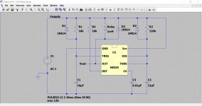
So I built the timer as per the suggested link and somehow the output is always low. I expect it to go high as soon as I turn on the supply so that the relay is de-energised. Any idea on where to look into?
Thanks again
Fabrizio
Attachments
I built the timer as per the suggested link and somehow the output is always low.
I expect it to go high as soon as I turn on the supply so that the relay is de-energised.
I would suspect C1, the timing capacitor. It must be a low leakage type,
or it will never charge to a high enough voltage due to its leakage.
Monitor the C1 voltage with a high impedance dvm, and see if its
voltage goes high enough to switch the timer.
Hi Ray,
If I understand correctly C1 is supposed to slowly charge, independently of Vout.
I looked into Vtrig (C2) and that follows the same profile of Vcc by turn-on.
According to the instructions that is supposed to stay low for a while in order to start the timing and trigget Vout high.
I wonder if C2 is the actual reason and how I can make it hold Vtrig down long enough.
Thanks
Fabrizio
Last edited:
I wonder if C2 is the actual reason and how I can make it hold Vtrig down long enough.
I can't look at this any more closely today, but if this is so try increasing C2
and/or the resistor feeding it.
The 555 is a terrific device but it does need care in implementation. The old (original) 555 which is still available behaves a little differently in practice compared to the later low power and CMOS versions.
So the first question is what type of 555 are you using.
Other issues concern the way the rail rises from power on... does it rise quickly or does it ramp up a little more slowly.
I've used the 555 very succesfully for muting circuits but you end up with something a little different to the text book implementations. A good circuit will also go into mute if the power drops out briefly and will then go on to give the full mute delay time before re-energising the relay.
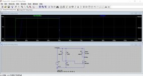
Another good option is a simply discrete delay circuit like these (left hand side of image). The power comes on 10 seconds in and the relay cuts in a few seconds later. Power off at 50 seconds. Increasing C1 will get you a longer delay.
So the first question is what type of 555 are you using.
Other issues concern the way the rail rises from power on... does it rise quickly or does it ramp up a little more slowly.
I've used the 555 very succesfully for muting circuits but you end up with something a little different to the text book implementations. A good circuit will also go into mute if the power drops out briefly and will then go on to give the full mute delay time before re-energising the relay.
Another good option is a simply discrete delay circuit like these (left hand side of image). The power comes on 10 seconds in and the relay cuts in a few seconds later. Power off at 50 seconds. Increasing C1 will get you a longer delay.
Attachments
Thanks Mooly and Ray.
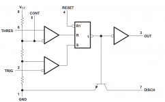
I discovered that in the first couple on/off cycles, the circuit above with the timer (NA555p from TI) works fine. After that, pin 7 (disch) is permanently shorted to ground. So it seems that the internal transistor (see pic) is fried...no idea what happens.
Mooly, your elegant delay circuit looks like a very good alterntive. My available Vdc is around 12V: can I use a voltage divider to get to the 5V? Or maybe just put a resistor in series to the relay to limit the current?
Thanks again
Fabrizio
Attachments

Going back to the 555
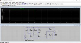
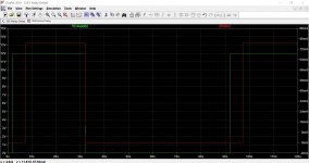
I just copied my 555 delay circuit (this is using an original LM/NE 555) into LTspice. The two timing diagrams show how the relay energises reliably on each power up cycle.
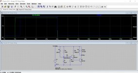
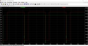
The last image shows the supply interuption down to just 100ms. The circuit still gives a correct on delay each time this interupt occurs.
For this circut to work reliably the 555 must be decoupled across the supply pins with a suitable cap... I always used a small electrolytic and never had issues.
I just copied my 555 delay circuit (this is using an original LM/NE 555) into LTspice. The two timing diagrams show how the relay energises reliably on each power up cycle.
The last image shows the supply interuption down to just 100ms. The circuit still gives a correct on delay each time this interupt occurs.
For this circut to work reliably the 555 must be decoupled across the supply pins with a suitable cap... I always used a small electrolytic and never had issues.
Attachments
- Status
- This old topic is closed. If you want to reopen this topic, contact a moderator using the "Report Post" button.
- Home
- Source & Line
- Analog Line Level
- where to place mute circuit?