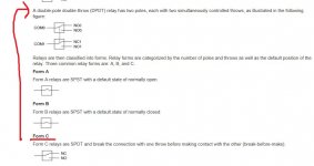
Yes, which would be too much.
The plates will draw little current though and so you could split the supply and add the resistor/cap combination to just the plate supply and leave the heaters alone and still fed from the full voltage. That would allow the resistor to be increased significantly.
The plates will draw little current though and so you could split the supply and add the resistor/cap combination to just the plate supply and leave the heaters alone and still fed from the full voltage. That would allow the resistor to be increased significantly.
Yes, much more effective. You could also increase the electrolytic cap values for the filter which would be perfectly acceptable.
What you don't want to do is add lots of capacitance directly (or via low value resistor feeds) to a typical SMPS supply. The high value resistor and cap is fine.
What you don't want to do is add lots of capacitance directly (or via low value resistor feeds) to a typical SMPS supply. The high value resistor and cap is fine.
Thanks mooly for answering all these questions. I’ll let you know how it turns when I get back into the case. If the light noise that I have now is the best that I can do I’d still be happy. It’s minimal really and only obvious with my ear by the drivers; I’ve owned noisier commercial products.
The mylar should be fine because the series resistor will even things out.
Its a bit like saying is a cap with 0.01 ohm ESR better than one with 0.04 ohm ESR. Answer yes, but add a 1 ohm series resistor and the difference disappears. We need the series resistor because of the unpredictable spiky nature of the SMPS noise.
Its a bit like saying is a cap with 0.01 ohm ESR better than one with 0.04 ohm ESR. Answer yes, but add a 1 ohm series resistor and the difference disappears. We need the series resistor because of the unpredictable spiky nature of the SMPS noise.
Ok. They say they are DPDT though. And I think I need two poles right? I am going to use two of them instead of four of the SIL.
C93418 TE Connectivity / Axicom | Mouser
C93418 TE Connectivity / Axicom | Mouser
Last edited:
I got all the parts installed and it works great. But, after about 10 minutes the inputs start randomly switching very quickly and the device turns on and off. Everything is fine up until then. Any ideas as to a cause for the instability?
The power supply does not appear to be switching on and off or going into protection.
I installed two dpdt 12v relays connected to a delay module for signal muting. Also the power supply filter rc circuits you recommended.
I know it’s hard to diagnose remotely with so little info, but let me know if you see a likely culprit. I’ll open it up again tomorrow and poke around.
Have you left pin 13 of the 4017 open, or is it connected to GND/VSS?I got all the parts installed and it works great. But, after about 10 minutes the inputs start randomly switching very quickly and the device turns on and off. Everything is fine up until then. Any ideas as to a cause for the instability?
I believe it is connected to gnd, but that might be 14. I grounded one or the other. The 4017 is now working as intended though.
I found the source of the instability. I am using an adjustable mini buck converter to take 12.6v from the 24v supply and an inductor (square type smd) was getting hot and causing the converter to switch on and off. I am probably drawing near the limit of it's amp rating with the various relays and the tube heaters all using 12v simultaneously. I drilled some holes in the bottom panel beneath in and also moved it so it could ventilate a bit better.
I will probably switch to a linear regulator now that I have the entire circuit working correctly. I have solid 1/4" aluminum dividers in the enclosure that should make a good heatsink for the regulator.
Here are the photos I promised.
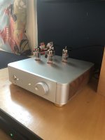
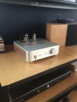
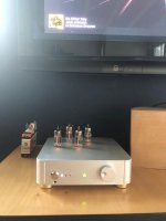
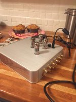
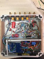
The gold feet will probably be replaced with silver, but I had them on hand. Right now it's just sitting on them; they aren't attached
The enclosure was WAY too small! Maybe for a two channel but four channel with with a couple of stereo inputs thrown in was a bit of a nightmare. It also has remote volume control and on/off, delayed signal muting and huge input and output caps (the caps in the picture were just spare parts I had and not all the correct values, but when I saw that it was going to work and sound good, I ordered and insalled Audyn Plus which barely fit.) Also, the muting circuitry went in after that pic.
BTW, the divider pieces square up once the bottom is attached. And the whole thing is really cleaner than it looks it's just so dang tight
Once again, thanks for everyone's help, especially Mooly. Considering that I don't know what I'm doing, I'm happy to say that it works exactly as planned and sounds better than it has any right too- very clean, detailed, airy and correct sounding, no tubbiness or overt warmth or congestion. And thanks to Shannon Park of Park Audio, the audio circuit was lifted from his Aduino Budgie preamp and just scaled for four channel.


The gold feet will probably be replaced with silver, but I had them on hand. Right now it's just sitting on them; they aren't attached
The enclosure was WAY too small! Maybe for a two channel but four channel with with a couple of stereo inputs thrown in was a bit of a nightmare. It also has remote volume control and on/off, delayed signal muting and huge input and output caps (the caps in the picture were just spare parts I had and not all the correct values, but when I saw that it was going to work and sound good, I ordered and insalled Audyn Plus which barely fit.) Also, the muting circuitry went in after that pic.
BTW, the divider pieces square up once the bottom is attached. And the whole thing is really cleaner than it looks
Once again, thanks for everyone's help, especially Mooly. Considering that I don't know what I'm doing, I'm happy to say that it works exactly as planned and sounds better than it has any right too- very clean, detailed, airy and correct sounding, no tubbiness or overt warmth or congestion. And thanks to Shannon Park of Park Audio, the audio circuit was lifted from his Aduino Budgie preamp and just scaled for four channel.
- Status
- This old topic is closed. If you want to reopen this topic, contact a moderator using the "Report Post" button.
- Home
- Source & Line
- Analog Line Level
- Help with one button relay input switching
