3X is translated to near 10dB. Proved practical enough with most amps and headphones. 17dB to 20dB is usually too much with modern digital sources.
thank you
I agree for the 10 db, enough and advance with the digital
with a line like this I have no problem connecting the power final to a volume potentiometer
I think I have found the fault. I measured voltage across the input to the bad channel and rather shockingly there is 8.6V. So I can only assume its the UPA68H that has failed or was bad when I put it in. Unfortunately I have no spares.
Looking on Ebay the chines ones are very cheap whereas the UK ones are pretty expensive. Can someone recommend a reliable source?
Thanks
Ian
Looking on Ebay the chines ones are very cheap whereas the UK ones are pretty expensive. Can someone recommend a reliable source?
Thanks
Ian
Looking on Ebay the chines ones are very cheap whereas the UK ones are pretty expensive. Can someone recommend a reliable source?
Thanks
Ian
That's not what you asked but avoid this sellers for any electronic components:
littlediode, utsource, polida
Thanks for all the advise on suppliers etc.
My main worry now is how to desolder the UPA76H. Even with solder braid, I am worried on how to get a 7 legged dual transistor package out without frying it or the board.
Ian
Better try with a desolder pump.
The braid is not good for this operation.
After a great deal of fiddling I got the UPA68H out and then tested it to find that J1 was dead, though J2 was ok. So I finally get an answer to the problem ")
I have a matched quad of 2sk170's (genuine) and its taking all my will power not to fit them! I will try and be patient and wait for the replacement UPA68H
Thank you for all the suggestions and help.
Ian
I have a matched quad of 2sk170's (genuine) and its taking all my will power not to fit them! I will try and be patient and wait for the replacement UPA68H
Thank you for all the suggestions and help.
Ian
I have a matched quad of 2sk170's (genuine) and its taking all my will power not to fit them!
What's wrong with 2sk170's ?
Simon
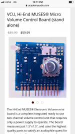
One of my friends got the muses volume Control board from academy Audio and wanted to pair with his salas I-select input control and dcg3 preamp. Below is the image of the board for your reference. Now coming to the connections little confused especially with the ComL and ComR and below is the quote from Mr.Lenny of academy Audio inc.
The VCU board works exactly as a dual gang pot. ComL and ComR are the separate common terminals for the Left and Right channels respectively. D-GND is a digital ground ( a reference point for the muting relay control ). After each channel is wired using their own common terminal as a reference, all three common terminals shall be connected together and to the ground point of the power supply.
The Mute output is needed to control the muting relay, which eliminates unwanted noises associated with the power-up and power-down processes.
How to wire up from the output L/Gnd/R of the I select input board and the input and outputs of the dcg3 preamps? I could get the input and outputs L/R but the common input and output grounds is where the confusions starts. Can someone point me to the right wiring as well as how to use the mute feature.
Thanks
Attachments
It is two different implementations of Muse chip, so wiring of one doesn't apply to the other.
The Com grounds you are referring are signal grounds which should be connected according to the instructions to the input of the preamp / ouput of the I-select and also with each other at one point and then (from that point) to the power ground of the muse psu.
My recommendation is to connect all power grounds together (Muse, I-Select, DCG3) and then via a loop breaker to the earth ground. You can add a small value resistor between each ground (each channel separately) and LB.
The mute control might just well be power switch for an external muting relay which automatically mutes output when you power up or down the muse control. If that's the case it doesn't act like a volume mute.
To clarify these things a simple manual should be provided by the manufacturer.
Last edited:
- Home
- Source & Line
- Analog Line Level
- Salas DCG3 preamp (line & headphone)