Instead of MOSFETs you can always use a diffamp as the current source. A part like the LT1990, INA154 (dual)
Silonex has an equation for fitting the response, or you can derive your own. In practice, you only need 3 points for a reasonable fit. You do have to measure, however, because the parts vary from piece to piece.
Silonex has an equation for fitting the response, or you can derive your own. In practice, you only need 3 points for a reasonable fit. You do have to measure, however, because the parts vary from piece to piece.
Hello Vincent,
I´ve only one objection in your design: the use of the chinese display; it is not really long term availability and for some people really hard to purchase.
My idea is to modify your design by adding a LCD touchscreen display over the I2C interface (A4 and A5 pins from Arduino): one board with µC, LDR, IO´s interconnected with a 1mm ZIF connector, or other type, to a second board with supplies and LCD (the encoder is superfluous).
The candidate for this display would be from ELECTRONIC ASSEMBLY. I´ve used successfully this type of LCD with touchscreen in military application, but sorry, I´m not programmer!
They provide also OLED displays but in this case only over SPI.
ELECTRONIC ASSEMBLY - root LCD Module
Ok, you have to do some firmware modification to implement the LCD.
I know that a lot of people will then positivelly interested in a GB...
Regards,
Jean-Paul
Hello Jean-Paul,
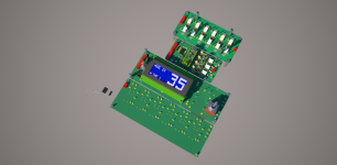
The i2C 2004 LCD display is really easy to get and cheap - there are hundreds for sale on eBay or in Arduino-related online shops (LCD Display Blue 2004 (20x4) IIC, I2C, TWI )
But of course, any i2C display can be used, if you adapt the software.
You have a cool project going on, keep us updated!
Could you possibly post photos of the input and power supply pcbs?
Hello,
I don't have photos of these pcbs because the ones I have are an earlier version - the ones published here have been modified/improved.
You can open the PCB file with Eagle to see exactly what it looks like and where each part should go!
Hello,
I don't have photos of these pcbs because the ones I have are an earlier version - the ones published here have been modified/improved.
You can open the PCB file with Eagle to see exactly what it looks like and where each part should go!
Thanks Vincent! I downloaded Eagle.
Thanks Vincent! I downloaded Eagle.
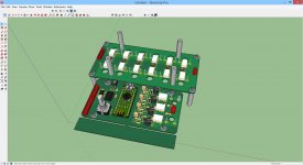
There is an even better way to see the PCBs: you go to 3D Gerber Viewer | Mayhew Labs and you drag and drop the GERBER files in the viewer there (extract them from the .ZIP first). Then you can see a 3D rendering of the board!
There is an even better way to see the PCBs: you go to 3D Gerber Viewer | Mayhew Labs and you drag and drop the GERBER files in the viewer there (extract them from the .ZIP first). Then you can see a 3D rendering of the board!
Thanks Vincent. Looking over your design in more detail today this is a very generous contribution indeed to the DIY community! Excellent work!
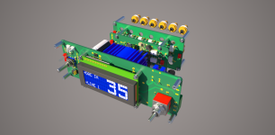
... work in progress...
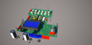
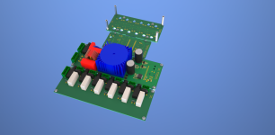
eDIP128B-6LWTP (with touchscreen); main power EMC filter and main power ON/OFF.
Fourth board in braining: RTC, elapsed time counter (super caps with charger), temperature sensor.
Missing something? I think about a current sensor? Anyone a schematics or tested circuit?
eDIP128B-6LWTP (with touchscreen); main power EMC filter and main power ON/OFF.
Fourth board in braining: RTC, elapsed time counter (super caps with charger), temperature sensor.
Missing something? I think about a current sensor? Anyone a schematics or tested circuit?
Attachments
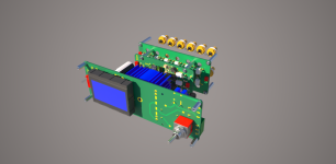
... work in progress...
eDIP128B-6LWTP (with touchscreen); main power EMC filter and main power ON/OFF.
Fourth board in braining: RTC, elapsed time counter (super caps with charger), temperature sensor.
Missing something? I think about a current sensor? Anyone a schematics or tested circuit?
Is this the display you are intending to use JP? It looks very nice but about 90 USD is quite expensive?
EA EDIP128B-6LWTP Electronic Assembly GmbH | 1481-1106-ND | DigiKey
You can also use the from Vincent recommended chinese LCD with free wiring!
I know this LCD very well then I use it in many military application, but you are right, it is not the cheapest!
I know this LCD very well then I use it in many military application, but you are right, it is not the cheapest!
You can also use the from Vincent recommended chinese LCD with free wiring!
I know this LCD very well then I use it in many military application, but you are right, it is not the cheapest!
Jp, I sincerely meant no offence to you with my previous remark. Just if you are heading towards a GB I think the cost may be a strong consideration for some people.
There is an even better way to see the PCBs: you go to 3D Gerber Viewer | Mayhew Labs and you drag and drop the GERBER files in the viewer there (extract them from the .ZIP first). Then you can see a 3D rendering of the board!
Thats a very nice gerber viewer Vincent! BTW, I have ordered 10 control PCBs and will try to verify your design...
@wineds
I will try to include the option "cheap chinese LCD".
I have the datas for the LCD.
Who can supply datas (dimensions, or better, 3D datas) for the YwRobot Arduino mezzanine board?
I will try to include the option "cheap chinese LCD".
I have the datas for the LCD.
Who can supply datas (dimensions, or better, 3D datas) for the YwRobot Arduino mezzanine board?
@wineds
I will try to include the option "cheap chinese LCD".
I have the datas for the LCD.
Who can supply datas (dimensions, or better, 3D datas) for the YwRobot Arduino mezzanine board?
I found some information in the attachment (see the PDF and XLS) :
http://www.selloutsoon.com/albums/documents/20-011-913/lcd2004.rar
Attachments
Jean-Paul asked how the I/O relay contacts are wired - see the attached examples.
The schematics are the same for input and for output channels (only the labels change, from "out" to "in".
For 2 inputs (or outputs), only one relay is used for both.
For 3 or more I/O, one relay is used for each input or output.
The schematics are the same for input and for output channels (only the labels change, from "out" to "in".
For 2 inputs (or outputs), only one relay is used for both.
For 3 or more I/O, one relay is used for each input or output.
Attachments
... finished!
Can you check the schematics? I want to order PCB' s (without fourth board: needs from customers more options and features!)...
Can you check the schematics? I want to order PCB' s (without fourth board: needs from customers more options and features!)...
Attachments

- Home
- Source & Line
- Analog Line Level
- Arduino based LDR volume and source selection controller