Yes, everything is controlled by the arduino nano and there are still enough arduino pins free for other duties.
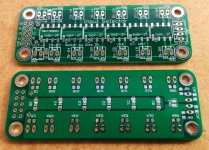
My attenuator PCBs can only accept SMD resistors (0805 imperial size). The closest you can come to the use of "audiophile" through hole resistors is using micro-MELF on 0805 pads. But I do not know if there are "audiophile" parts in such a package. I am fine with the standard thin(metal)-film resistors of better than 0.5% tolerance and reasonably low temperature coefficient. The PCB heats up by few degrees only due to heat dissipation in relay coils and thus there is no need to be extreme here. The heat distribution is also more or less uniform and thus symmetric across the channels due to symmetric PCB layout.
The balanced attenuator is on the to-do list.
If you need through-hole attenuator design have a look at the amb offer.
Edit: amb website is down at the moment but will be online soon. The owner has mentioned this in the other thread.
Regards,
Oleg
Last edited:
Vishay Beyschlag MMA0204, 1%, 50ppm have shown some favorable noise results when measured by the LIGO guys:
https://dcc.ligo.org/public/0002/T0900200/001/current_noise.pdf
and TME have them
0204 minimelf smd resistors | Transfer Multisort Elektronik - Electronic components
https://dcc.ligo.org/public/0002/T0900200/001/current_noise.pdf
and TME have them
0204 minimelf smd resistors | Transfer Multisort Elektronik - Electronic components
Attached is my arduino code. It is working as intended but will need further adjustments depending on the way the IR remote control feature is used and other minor things. It is not the most elegant implementation but as long as it works without hiccups I have no drive to further optimize it. Nevertheless, as I progress with my attenuator assembly I'll post code updates as they come.
The code has dependencies on external libraries for IR remote control
GitHub - cyborg5/IRLib2: Library for receiving, decoding, and sending infrared signals using Arduino
and LCD display
fmalpartida / New LiquidCrystal / Downloads — Bitbucket
Big thanks to maxw for sharing his code with diyaudio community from which I learned a lot when I started.
Regards,
Oleg
Attachments
I'm having some problems with the Arduino library IRLib2. When I try to run the code I get this kind of error message in IDE:
"In file included from C:\Program Files (x86)\Arduino\libraries\IRLib2/IRLibAll.h:22:0,
from AttenuatorArduinoCode.ino:2:
C:\Program Files (x86)\Arduino\libraries\IRLib2/IRLibDecodeBase.h:13:28: fatal error: IRLibProtocols.h: No such file or directory
#include "IRLibProtocols.h"
^
compilation terminated."
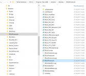
I have downloaded the IRLib2 library from GitHub and my libraries folder looks like in the attached screen shot. I think I do have the "IRLibProtocols.h" file, but it still doesn't work. Please help as I'm an Arduino noob.
"In file included from C:\Program Files (x86)\Arduino\libraries\IRLib2/IRLibAll.h:22:0,
from AttenuatorArduinoCode.ino:2:
C:\Program Files (x86)\Arduino\libraries\IRLib2/IRLibDecodeBase.h:13:28: fatal error: IRLibProtocols.h: No such file or directory
#include "IRLibProtocols.h"
^
compilation terminated."
I have downloaded the IRLib2 library from GitHub and my libraries folder looks like in the attached screen shot. I think I do have the "IRLibProtocols.h" file, but it still doesn't work. Please help as I'm an Arduino noob.
Attachments
I'm having some problems with the Arduino library IRLib2. When I try to run the code I get this kind of error message in IDE:
"In file included from C:\Program Files (x86)\Arduino\libraries\IRLib2/IRLibAll.h:22:0,
from AttenuatorArduinoCode.ino:2:
C:\Program Files (x86)\Arduino\libraries\IRLib2/IRLibDecodeBase.h:13:28: fatal error: IRLibProtocols.h: No such file or directory
#include "IRLibProtocols.h"
^
compilation terminated."
I have downloaded the IRLib2 library from GitHub and my libraries folder looks like in the attached screen shot. I think I do have the "IRLibProtocols.h" file, but it still doesn't work. Please help as I'm an Arduino noob.
I have no experience with arduino IDE on Windows, since I work on Linux most of the time, but I see that there is directory separator problem in the error message that you get. I highlighted the problematic parts: backslash (Windows style) change to a slash (Unix/Linux style). Maybe this is the problem.
Regards,
Oleg
Ok, so where should I try to change the directory separator? In your attenuator code or in the IRLib2 library? I don't remember facing this kind of problems with my earlier Arduino experience: Arduino based LDR volume and source selection controller
I highlighted the problematic parts: backslash (Windows style) change to a slash (Unix/Linux style). Maybe this is the problem.
YAY!! I got it working quite ok after I updated my ancient IDE version 1.6.1 to the latest 1.8.5. Also my Chinese LCD display had a different I2C address than what was on the original code. I changed this in the code (bold):
"LiquidCrystal_I2C lcd(0x27,2,1,0,4,5,6,7); // Set the LCD I2C interface"
Now I think it's just my encoder (Bourns PEC11R series) that needs the resistors and capacitors as described in the datasheets. Now it's like a machine gun when I turn the encoder.
The IR functionality I didn't test. What kind of remote control do I need for it? I have an old Logitech Harmony 555 remote that I can learn the commands if I just knew what to look for.
Congrats for the first successful steps") What you experience with the encoder is probably its contacts bounce, so RC filters recommended in the datasheet should fix it.
What you experience with the encoder is probably its contacts bounce, so RC filters recommended in the datasheet should fix it.
The remote can be any which has carrier frequency similar to your IR receiver. Using serial terminal you can learn all the necessary button codes and add extra "cases" to the "switch" clause to do the necessary functions.
What you experience with the encoder is probably its contacts bounce, so RC filters recommended in the datasheet should fix it.The remote can be any which has carrier frequency similar to your IR receiver. Using serial terminal you can learn all the necessary button codes and add extra "cases" to the "switch" clause to do the necessary functions.
Cleaned up and slightly optimized the code. Also implemented the input selection by using the numbers on the IR remote and standby mode (turns the LCD off, releases all relays which effectively sets max attenuation and mute, and disconnects all inputs). So far standby is only triggered by the remote control. In the future it should also be possible to engage by a long button press on the front panel.
Regards,
Oleg
Regards,
Oleg
Attachments
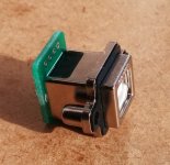
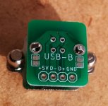
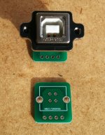
To minimize the space the USB input takes inside the chassis I found a nice rugged USB-B socket from Amphenol (mouser part number: 523-MUSB-D511-N0). To make connection convenient I also designed a small adapter PCB for it (see attached).
Regards,
Oleg
Regards,
Oleg
Attachments
- Home
- Source & Line
- Analog Line Level
- R-2R attenuator PCB layout question