Hi Max,
Big part of your compliment goes back to you, since I've been greatly inspired by your designs! 🙂
Regards,
Oleg
Big part of your compliment goes back to you, since I've been greatly inspired by your designs! 🙂
Regards,
Oleg
Hi Oleg,
nice compact set of PCBs. Are you going to offer them here? or is it possible to get the gerbers.
For the firmware of the input selector display,one suggestion. I prefer the real name of the selected input in the display. Is that possible?
Best regards
Günni
nice compact set of PCBs. Are you going to offer them here? or is it possible to get the gerbers.
For the firmware of the input selector display,one suggestion. I prefer the real name of the selected input in the display. Is that possible?
Best regards
Günni
Thanks for the good words, Günni!
I usually offer my PCBs here on the forum after I test them. As for the real input names, it can easily be done by modifying few code lines. Since I personally have no good idea what will be connected where in my system I prefer numbered inputs for a time being, but since I plan to make the source code of the firmware public, it should be easy to make a custom version of it.
Regards,
Oleg
Cool project! I’m definately interested to aquire the boards if you will offer them at some point.
Last edited:
Thanks, Morde!
I'm currently testing the attenuator to make sure that it really is clean and does not produce clicks and pops in all possible regimes, e.g muting/unmuting, changing attenuation, especially when it crosses through 01111 -> 10000 state and also when changing inputs at various volume settings. I'll report when I am done and if everything is OK then the boards will be available.
Regards,
Oleg
Nice PCB work.Thanks, Morde!
I'm currently testing the attenuator to make sure that it really is clean and does not produce clicks and pops in all possible regimes, e.g muting/unmuting, changing attenuation, especially when it crosses through 01111 -> 10000 state and also when changing inputs at various volume settings. I'll report when I am done and if everything is OK then the boards will be available.
Regards,
Oleg
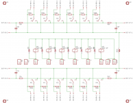
As a matter of fact, this is not an R-2R attenuator but a logarithmic attenuator where all resistors have different values and also the topology is quite different.
To avoid pops or transients when changing volume, especially when going from 01111 to 10000 or vice versa, you should do as follows:
With every volume change go in between for about 4 msec to 00000, assuming that 00000 is the max attenuation.
You will not notice this 4 msec step in between, but all pops will be prevented.
So going from 01111 to 10000 will have to go like 01111 - 00000 - 10000.
Succes,
Hans
Hi Hans,
Thanks for your comments. I totally agree that the name for the attenuator topology is not entirely correct. I just accepted what was previously used by others for similar attenuators, but I guess it simply has historical roots due to some similarity to a classical R-2R resistor ladder ADC.
The algorithm to avoid pops and clicks that you mention is exactly what I did in my earlier setup more than a year ago. In the case of this new setup I managed to get away without muting in between the steps so far. The key is that engage and release timing of the relays that I use is nearly the same with release being a tiny bit slower, and thus the new setting engage slightly before the previous setting releases. I just wanted to experiment further to see if it is always like this. Otherwise I'll put back the mute before switch code.
Regards,
Oleg
Edit: it seems that it must be that the release time of the relays is faster than the new setting is engaged for pop and click free operation in the new setup.
Last edited:
I played with the attenuator a bit. It really works pops and clicks free so far. Also muting/unmuting and changing inputs at various volume settings is trouble free. The firmware is a bit too slow for comfortable use, so I'll try to optimize it a bit.
Since hardware works as intended and there is some interest in my PCBs I'll probably open a dedicated thread in commercial sector of the forum and offer the PCBs there. In the meantime simply PM me if you are interested in getting the PCBs before the firmware is ready or if you plan to write your own code.
Regards,
Oleg
I played with the attenuator a bit. It really works pops and clicks free so far. Also muting/unmuting and changing inputs at various volume settings is trouble free.
Congrats!
The firmware is a bit too slow for comfortable use, so I'll try to optimize it a bit.
Be sure to disable/remove Serial and Serial.print when not debugging your code as this slows down the code execution. I used a boolean for this. e.g.
Code:
void setup() {
  ...
  // Serial
  if (debugEnabled) {
    Serial.begin (9600);
  }
  ...
}

void loop() {
  ...
  if (debugEnabled) {
    Serial.print ("Selected Input: ");
    Serial.println (selectedInput);
  }
  ...
}Thanks for the hints, Max!
Just did what you suggested, I had serial interface always running since using it for debugging the remote control codes. Unfortunately disabling it did not help. I guess I have some other issue since when I turn the encoder relatively quickly the relays start to chatter. This does not produce any artifacts in audio output and the volume is changing in the right direction, just a bit slower. I guess at some moment arduino loses state changes of the encoder and misread forward/backward rotation. This results in repeatedly setting neighbor volume settings back and forth until the right sequence is detected again.
Note, I use relatively high resolution encoder with 64 pulses per revolution which means it has 256 steps which I reduce to 32 attenuation steps.
Regards,
Oleg
Problem solved. I just rearranged the LCD code and reduced unnecessary and repeated writes to the display.
Hi ElFishi,
Both are from ebay. Here are the links for the enclosure (comes with the knob which I did not like) and the massive aluminum knob. The problem with this enclosure is that the holes for the inputs are spaced 14 mm apart while most of standard RCA connectors require minimum 16mm spacing. So after a long search I found these RCA combos which fit the 14mm spacing. You'll have to make the holes 0.5~1mm wider but otherwise they fit well.
Edit: LCD display mounting holes are also nonstandard, so I had to drill new blind holes and tap threads by myself.
Regards,
Oleg
Last edited:
I had seen that enclosure, too. Thanks for pointing out the spacing glitch, very helpful.
Did I get you right, the front plate of that enclosure does have tapped holes, but not in the standard positions? Sad.
Did I get you right, the front plate of that enclosure does have tapped holes, but not in the standard positions? Sad.
Did I get you right, the front plate of that enclosure does have tapped holes, but not in the standard positions? Sad.
Yes, the front panel has tapped holes but in the nonstandard positions. This makes it possible to design a custom backplate and mount the LCD display on it together with the IR receiver and other controls.
Regards,
Oleg
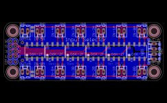
I decided to better "align" input selector with the attenuator PCB. This resulted in a 6-way input selector with the same footprint as the attenuator. I've added one extra pair of outputs to the input selector PCB which are in registry with the attenuator inputs. Depending on the actual chassis layout one or the other output pair of the input selector can be used.
Regards,
Oleg
Regards,
Oleg
Attachments
- Home
- Source & Line
- Analog Line Level
- R-2R attenuator PCB layout question