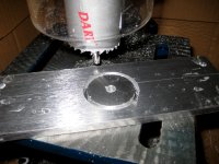
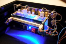
Well I was having trouble finding a chassis I liked so I decided to make a quick LM1875 gainclone in the mean time. Initial tests with the Arduino and Attenuator work really well!
Attachments
Got mine working last night with I2C 2x16 LCD and a proto shield. I still have to connect the PGA chip though. I will be using PGA2311 and I still need to build the input selection relay board. I will post some pictures of what I have done so far, later today. The problem I am having I think is in the rotary encored reading routine, as reading seem to bounce too much. There is a way to do de-bouncing in SW, so I will look into that and post my findings and a possible fix. Thanks maxw for the original source code. Are you still working on improving the code?
/R
/R
Thanks maxw for the original source code. Are you still working on improving the code?
/R
Yeah defo, I only really used that code for testing, I'll work on it more soon. I've seen a debounce library about, have a search, might be useful although I've had no problems as is.
Max,
This is exactly what I'm looking for. Would you be willing to post the gerber files you used?
Here are the eagle files. I also have some spare PCBs/Parts if you wish.
Attachments
Here are the eagle files. I also have some spare PCBs/Parts if you wish.
That would be awesome.
I'm planning to use your controller and attenuator board (I'll try totally passive at first) with an Osram display hooked up to a ClassDAudio amp. I've played with the Arduino a bit before, but this is my first audio project - hope I haven't bitten off more than I can chew ...
Could you PM me with the details (the cost for the boards and/or any extra parts you might have, PayPal info, etc.)?
I'm working on something similar, but less complicated:
I'm building various audio devices, which need volume/input controls, but with different input/display/control hardware.
In example, as a volume control, i could use motor alps, motor alps with feedback thru one of the potentiometer channels, relay attenuator (different approaches of control - direct pin, shift reg, inversed 1 and 0 etc, different amount of relays)...
I do everything predefined in DEFINE section - pin numbers of I/O, and hardware type.
I want to make it multiplatform (different arduino boards) - sometimes i need just the basic moto alps without feedback + IR remote of + and - volume, sometimes - relay att via shiftregister, nixie display, rotary encoder, IR, input selector, etc...
I already have
- IR
- relay att (with shiftreg/direct, 5-8 relays)
- PGA
- ALPS without feedback
- input selector (both with decoder and direct), up to 8 inputs
+ Event based buttons routine
Could you share your source "as-is"? I'll share mine when i'll come back home.
I'm interested in rotary encoder and button debounce source...
Thanks!
Here are the eagle files. I also have some spare PCBs/Parts if you wish.
I would like to order a pair of PCBs please.
YES! More arduinio's in audio!
I am using a ChipKit Uno32 for my DAC project. The Uno32 has an 80mhz PIC processor running arduino on board! and 42 pins of I/O and ONLY $26!!!
For my DAC the Uno32(arduino) is controlling the power up functions with time delay and mute/unmute controls. input source selection and It counts word clock pulses and then likes one of six LED's according to sampling frequency in real time. So if you are playing a 44.1khz CD that LED lights. if you switch to 192khz hi rez files, the 192 LED lights!
next I will be learning some Sony remote control IR codes for remote control implementation.
Arduinos are perfect for pre-amp control etc!
I know linuxworx here and AMB has done a LOT with arduinos and Atmega Processors and has some excellent pictures and info!
Zc
I notice your relays have no protection diodes, Are these needed? also On your schematic you have 5v connected to to of the ic2 pins through resistors , what are these for and what value should they be.
I didn't bother with them and it seems work fine.
Those resistors are the I2C pull up resistors. Mine are 4.7K but they can be any value from around 1k to 47k. Google it, plenty of articles.
YES! More arduinio's in audio!
I am using a ChipKit Uno32 for my DAC project. The Uno32 has an 80mhz PIC processor running arduino on board! and 42 pins of I/O and ONLY $26!!!
For my DAC the Uno32(arduino) is controlling the power up functions with time delay and mute/unmute controls. input source selection and It counts word clock pulses and then likes one of six LED's according to sampling frequency in real time. So if you are playing a 44.1khz CD that LED lights. if you switch to 192khz hi rez files, the 192 LED lights!
next I will be learning some Sony remote control IR codes for remote control implementation.
Arduinos are perfect for pre-amp control etc!
I know linuxworx here and AMB has done a LOT with arduinos and Atmega Processors and has some excellent pictures and info!
Zc
Nice. Post some pics!
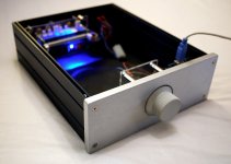
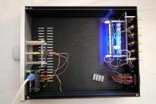
I made a new case, I'll post some new pics soon.
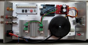
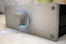
Here is my new case. I've opted for a completely passive input selector and attenuator for now. Both controlled by the arduino. Pics don't show the PSU but its just a small toroid and 5V regulator ")
Attachments
Beautiful!
But how do you know what setting you are at, in terms of both input and volume level? You would probably need a lcd display for that.
Also, a bit off topic: What camera are using? I ask because the noise shape reminds me a lot of the SIGMA slr, and no other digital camera that I know of can render this film look.
But how do you know what setting you are at, in terms of both input and volume level? You would probably need a lcd display for that.
Also, a bit off topic: What camera are using?
I ask because the noise shape reminds me a lot of the SIGMA slr, and no other digital camera that I know of can render this film look.Great work, Max!
I like the plexy and arduino mounting ideas!
Beautiful!
Thanks!
But how do you know what setting you are at, in terms of both input and volume level? You would probably need a lcd display for that.
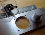
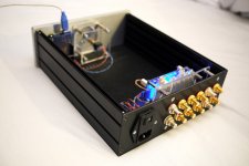
Well I did a lot of thinking about this and basically I think standard LCDs look tacky and cheap. I wanted something minimal that looks nice. I also figured that I don't really need to know what input I have selected if I can easily cycle through them in a loop until I hear what I want.
What I have done is set up a BlinkM that changes colour with the volume level. This is behind the volume knob, inside the case. It is an I2C controlled RGB LED. So it goes from Blue>White>Red as the volume gets higher. It's a really nice effect and I think works well. The encoder is also a push button momentary switch that changes the input.
Also, a bit off topic: What camera are using?
It's a Panasonic GF1 with 20mm pancake lens. Old but still my favourite camera!
- Home
- Source & Line
- Analog Line Level
- My Preamp Project: Arduino, I2C, relay selector+attenuator, tube stage