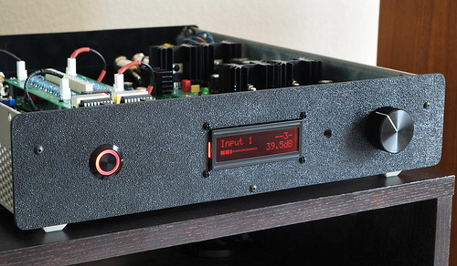
What I have done is set up a BlinkM that changes colour with the volume level. This is behind the volume knob, inside the case. It is an I2C controlled RGB LED. So it goes from Blue>White>Red as the volume gets higher. It's a really nice effect and I think works well.
Nice!
I was looking at a similar led/gadget at Sparkfun and, no matter how hard I tried, I couldn't come up with anything useful for it...
I guess some people are more imaginative than others.. 😱
Btw, I think it could be even cooler if it changed color every time you changed source (like Blue illumination = Input 1, Red = Input 2, Green = Input 3 etc.) and have the brightness of the specific LED color "simulate"/follow the volume setting. 😀
Btw, I think it could be even cooler if it changed color every time you changed source (like Blue illumination = Input 1, Red = Input 2, Green = Input 3 etc.) and have the brightness of the specific LED color "simulate"/follow the volume setting. 😀
Ha could do! It would be easy to implement. That's what I like about working with the Arduino, its so quick and easy to work with or add new features 🙂
Hi, very nice job !
I'm working around a similar project, my "digitally controlled" preamp is controlled by a board equipped with an ATMega32 that I've developed time ago.
The input selection is made through a touchscreen LCD (320x240 256 colors) where it is also shown the volume level (controlled by an optic rotary encoder and a PGA2310) in dB and through a graphical scale.
Max and min volume levels are set through software (in a "settings page") and the PGA basically replaces the analog potentiometer of the analogic preamp "P97" by Rod Elliot.
The input selection, mute and power on/off of the analogic section is done using some relays through a 74HC595 (8 bit serial-to-parallel converter shift-register) and a ULN2803 driven by the ATMega32.
The firmware is not complete yet but the basic functions are already working.
Regards,
Roberto
Hi, very nice job !
I'm working around a similar project, my "digitally controlled" preamp is controlled by a board equipped with an ATMega32 that I've developed time ago.
The input selection is made through a touchscreen LCD (320x240 256 colors) where it is also shown the volume level (controlled by an optic rotary encoder and a PGA2310) in dB and through a graphical scale.
Max and min volume levels are set through software (in a "settings page") and the PGA basically replaces the analog potentiometer of the analogic preamp "P97" by Rod Elliot.
The input selection, mute and power on/off of the analogic section is done using some relays through a 74HC595 (8 bit serial-to-parallel converter shift-register) and a ULN2803 driven by the ATMega32.
The firmware is not complete yet but the basic functions are already working.
Regards,
Roberto
Sounds good! Post some pictures.
Agree that the LCD displays are tacky.
You ever consider using a Sure 8x32 LED matrix?
in action: HT1632-AVR + Arduino + DE-DP104 on Vimeo
Could look similar to the display on the SimAudio Moon Evolution preamps: http://www.simaudio.com/images/xlg_moon600i.jpg
You ever consider using a Sure 8x32 LED matrix?
in action: HT1632-AVR + Arduino + DE-DP104 on Vimeo
Could look similar to the display on the SimAudio Moon Evolution preamps: http://www.simaudio.com/images/xlg_moon600i.jpg
Yeah, that's one of the many impressive builds at your blog, glt.
Proves that with enough creativity (and running around to get things done), DIY can match commercial gear. 😉
Max,
What are the impedance specs of your attenuator?
I'm considering using it along with a Salas DCB1 buffer (which is optimally paired with a 10-20k pot).
Proves that with enough creativity (and running around to get things done), DIY can match commercial gear. 😉
Max,
What are the impedance specs of your attenuator?
I'm considering using it along with a Salas DCB1 buffer (which is optimally paired with a 10-20k pot).
Last edited:
Agree that the LCD displays are tacky.
You ever consider using a Sure 8x32 LED matrix?
in action: HT1632-AVR + Arduino + DE-DP104 on Vimeo
Could look similar to the display on the SimAudio Moon Evolution preamps: http://www.simaudio.com/images/xlg_moon600i.jpg
That LED matrix is massive!
LCDs are cheap but can look real good:
More HIFIDUINO…in SERBIA H i F i D U I N O
That is the example I was going to post as it neatly shows the problem with LCD screens - Yes they can look really nice BUT the front panel must be machined to fit the LCD perfectly. Having access to machining tools is a luxury I don't have. I think you need to know someone otherwise the tooling and set up costs are crazy! Cutting a nice circle using a hole saw with my drill press is about the extent of my tools

This is the kind of implementation that makes me dislike LCD screens:
DIY: AMB/linuxworks labs alpha10 audio preamp | Flickr - Photo Sharing!
Max,
What are the impedance specs of your attenuator?
I'm considering using it along with a Salas DCB1 buffer (which is optimally paired with a 10-20k pot).
It's the same schematic/specs as the AMB Delta:
The δ1 Relay-based R-2R Stereo Attenuator
I think my current one is around 20k.
That is the example I was going to post as it neatly shows the problem with LCD screens - Yes they can look really nice BUT the front panel must be machined to fit the LCD perfectly. Having access to machining tools is a luxury I don't have. I think you need to know someone otherwise the tooling and set up costs are crazy! Cutting a nice circle using a hole saw with my drill press is about the extent of my tools
This is the kind of implementation that makes me dislike LCD screens:
DIY: AMB/linuxworks labs alpha10 audio preamp | Flickr - Photo Sharing!
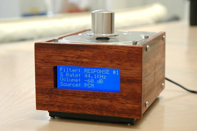
Totally agree. But if you use wood and a steady hand you can get something like this:
Your implementation of a colored LED to indicate volume level is a great idea!
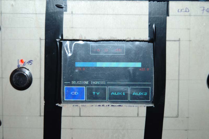
This is a pic (sorry for the poor quality and reflections) of the actual "user interface" of my preamp:
The preamp is still into the "prototype phase" (as you can clearly see 😀 ) but basic functions are already working.
"Selezione Ingressi" means for "Input Selection" and it is done by "clicking" with the finger on the correspondant icon.
Clicking on the volume level box activates the MUTE.
The volume is set by using a PGA2310 and an optic encoder, the balance function is made by regulating individually the volume of the desired channel.
Min and max value of the volume (shown in the "volume bar") are set in the configuration page (still in development) and the "volume bar" steps are calculated according to these values so that it reflects the actual volume level.
The volume level displayed in the box is calculated considering the total gain of the "analogic" preamp but this value will be "fine" adjusted when everything will be completed measuring the gain with an oscilloscope.
An externally hosted image should be here but it was not working when we last tested it.
The preamp is still into the "prototype phase" (as you can clearly see 😀 ) but basic functions are already working.
"Selezione Ingressi" means for "Input Selection" and it is done by "clicking" with the finger on the correspondant icon.
Clicking on the volume level box activates the MUTE.
The volume is set by using a PGA2310 and an optic encoder, the balance function is made by regulating individually the volume of the desired channel.
Min and max value of the volume (shown in the "volume bar") are set in the configuration page (still in development) and the "volume bar" steps are calculated according to these values so that it reflects the actual volume level.
The volume level displayed in the box is calculated considering the total gain of the "analogic" preamp but this value will be "fine" adjusted when everything will be completed measuring the gain with an oscilloscope.
This is a pic (sorry for the poor quality and reflections) of the actual "user interface" of my preamp:
The preamp is still into the "prototype phase" (as you can clearly see 😀 ) but basic functions are already working.
"Selezione Ingressi" means for "Input Selection" and it is done by "clicking" with the finger on the correspondant icon.
Clicking on the volume level box activates the MUTE.
The volume is set by using a PGA2310 and an optic encoder, the balance function is made by regulating individually the volume of the desired channel.
Min and max value of the volume (shown in the "volume bar") are set in the configuration page (still in development) and the "volume bar" steps are calculated according to these values so that it reflects the actual volume level.
The volume level displayed in the box is calculated considering the total gain of the "analogic" preamp but this value will be "fine" adjusted when everything will be completed measuring the gain with an oscilloscope.
Very cool, love it. The cardboard and tape front looks good too 😀
Did a library come with the touch screen? Or did you have to write your own?
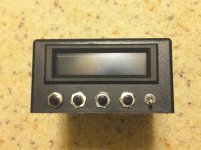
For a temp sensor project a little while back, I made this, using a hand drill, nibble and a file.
Bought the bezel from Digikey or Mouser, uses a standard 2x16 LCD, connected to an Arduino.
It also has a bluetooth interface, so I can get info through bluetooth to a Processing program running on a laptop. I have a switch to select USB or bluetooth on the arduino.
Randy
Bought the bezel from Digikey or Mouser, uses a standard 2x16 LCD, connected to an Arduino.
It also has a bluetooth interface, so I can get info through bluetooth to a Processing program running on a laptop. I have a switch to select USB or bluetooth on the arduino.
Randy
Attachments
Did a library come with the touch screen? Or did you have to write your own?
Unfortunately not, I had to write everything by my own, included a font to display text messages but it's not complicated.
To manage the touch capability you need 4 ADC (analog to digital converter) to read a voltage that is proportional to the position of the screen where you touched.
It communicates with the micro through an 8 bit bus and has some control lines, the only command that you need is to send it the coordinates of the pixel that you want to turn on and the color of the pixel.
Actually to turn off a pixel you just need to send the color "0" (black).
The negative side of using color (graphic) LCD is that they need a lot of kbyte if you want to display a bitmap.
In my case to display a full 320x240 (256 colors) bitmap I would need 76800 bytes since every pixel is represented by its color that is codified with one byte or 8 bit (RRRGGGBB).
Last edited:
You can get a completely free high end graphics library from NXP that will run on any of it's ARM controllers. Go onto their website and look und MCU. The manual is 1000 pages long and is based on the Segga GL. The library includes full touch screen support.
Hi Max,
I have taken your attenuator/selector code to start with for my R-2R attenuator as you once suggested me in my thread. I am currently looking through the code lines and am a bit confused by the need for bits manipulation in nibbleShift() function. Why not just send to the MCP23008 the binary values for the corresponding attenuation levels? E.g. send 0000 0001 for "1", 0000 0010 for "2", 0000 0011 for "3", ... , 0010 0000 for "32", etc. In my naive view this would correspond to the right sequence of relay switching, or am I missing something?
Regards,
Oleg
- Home
- Source & Line
- Analog Line Level
- My Preamp Project: Arduino, I2C, relay selector+attenuator, tube stage