Well done indeed - quite an impressive result
Now that the design of the "Base Module" is complete, can let your mind run free on some of the different applications, and not just a simple pot ....
One thing I meant to ask awhile back is if the program has room to include a balance control, maybe only a +/-10db (ie a left <-> right adjustment)
Now that the design of the "Base Module" is complete, can let your mind run free on some of the different applications, and not just a simple pot ....
One thing I meant to ask awhile back is if the program has room to include a balance control, maybe only a +/-10db (ie a left <-> right adjustment)
One thing I meant to ask awhile back is if the program has room to include a balance control, maybe only a +/-10db (ie a left <-> right adjustment)
James, that's already included in the design -- there are three jumper selectable operational modes: Calibrate, Dual Mono, and Stereo (volume + balance).
In the Dual Mono mode the channels are independent and could be used for 5.1 or 7.1 or even something like a 100 channel mixing board.
At one point I had planned jumper selectable log or linear pot for volume but decided against it because different log pots have different break points for the typical two linear sections, and it would have been impossible to emulate the variety of those pots accurately in software.
Last edited:
Have just run the calibration routines with different target values and "built" both a 50K and a 100K pot from the same LDRs that I've been using to build 10K pots. The 100K is pushing the limit for a pot starting at the low end of resistances due to the span of values and control becomes sloppy well before 100K at around 80K, but at 100K the result is a 70dB pot. Ha!
Selected LDRs could no doubt be used to create an even higher resistance pot, but you'd have to sacrifice the low values somewhat.
Actually, lowering the maximum current from 11.5ma to 10ma would sacrifice a few ohms at the bottom but probably would then give better control at the 100K end and lead to a better 100K pot.
I don't think anyone in the audio end will complain about getting a better than 70dB result for a 100k pot, but maybe in the pro area or just for a marketing exercise! It's quite an achievement in itself as an academic exercise.
I had another thought (I do occasionally!) about using these units as matched filter resistors similarly to Uriah's 'resistor replacer' but with the calibrated precision and matching - I inserted a pair of Uriah's little units into a pretty good amp, as replacement for PRP resistors, just out of curiosity, and was very surprised at the improvement in clarity and etc in the sound
Most of the more readily available precision resistors are pretty expensive (Vishay, Neohm, Rhopoint, etc) so something that's not a ridiculously expensive alternative, particularly if the ability to cross couple more than one, could be a very viable option - many of us are 'quite serene' about parting with quite significant $s for good quality pots ....
Yes Andrew, just the 10dB reduction facilty would be quite right, as it's unity/lo gain device - thanks for that - good to see it's already incorporated.
Actually, while I've got your attention, you're in a position to find out the benefits of using "T-Pads" as an improvement over "L-Pads" - any thoughts on this ...?
Years ago, we always used 'T Pads' in critical areas (stepped attenuators, speaker level controls, etc) so I tried to cobble up a simple Vol control setup using Uriah'c LighterNote control but had trouble sorting out the matched devices, current distribution, etc and couldn't make any determination about any practical benefits in comparison to just using the impedance matching ability of his circuit.
James, you're talking about using three LDRs per channel? For a stereo pair that would require a bigger chip than I'm using -- presently I don't have enough control pins to manage that that. Also the question would arise as to the efficacy of asking a single processor to handle the precision control of six devices which would be a 50% rise in overhead as compared to the four devices I presently control. So, in practice it would probably result in a smaller chip handling three devices instead of a larger chip handling six devices. I.e., a chip per channel, not a chip per stereo set.
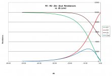
What do the resistance curves look like for such a device? And, at this point in history, is there still a demand for such a device?
James, what potentiometer value is ideal for transistor amps? I assumed that it was 10K, but have I got it wrong? Here is my spreadsheet-based impedance calculations for a 10K pot. These curves assume a 200 ohm source impedance and a 10K load impedance. The curves do change slightly with changes in source and load.
Attachments
Last edited:
A common T-Pad arrangement uses the 2 series resistor of the same value but as each ldr requires it's own control module, then yes, would need the whole stereo module for each channel of the T-Pad -
However, if you had a pair of the series ldrs that have a close enough impedance curve, then the 1 control module could be used to drive both series ldrs, assuming there isn't much 'current hogging' of the parallel units across the range of operation - not at all sure about this ...
You could also control the second series resistor with it's own 'curve', but that's probably left for another day - just a concept idea to maybe include in module control/layout/etc.
I don't think the demand for a 'T-Pad' will be at all high, but if it's available and at a reasonable cost, there are some situations/designs that'll immediately benefit from the use of a 'better' attenuator
The T-Pad/network is basically an arrangement that offers a more controlled impedance for both the source and the load -
With the L-pad, the normal load line presents a controlled impedance in just the one direction - with your pretty amazing curves about, the source sees an impedance of 10kR until nearly 10dB attenuation (nearly full volume) with source Z of 200R and a load of 10kR and only drops to about 5kR at full volume - pretty amazing effort
Now, the output impedance is quite low until again nearly full volume, so this thing of yours will have very little trouble at all driving some of those classD amps (some down to around 3kR input Z these days) - most amps present 20kR up to 100kR, altho a few go down to 10kR.
Valve circuits seem to be going thru a revival these days and the input Z of most of these is usually up around the 100kR - however, the outputZ on many can be up around the 1kR mark and if the vol pot is located after the gain stage (or more commonly a buffer, for example), then the inputZ of your device as described above, is just fine.
My Aikido buffer stage has an outputZ about 800R, for example, and the common setup with a CEN output stage of a Dac is 1500R so that would probably also be okay to have your attenuator fitted straight on after, without any buffer.
What's with the T-Pad - well, the 3 'legged animal' has the ability to present a more controlled impedance both input and output - so it's easier to design a more linear input Z without being all too concerned about the load, and vice-versa - more flexibility, really
Nowadays, with the price of electronics being quite low, adding a stage is cheaper and simpler than adding another resistor, and power supply requirements are usually ignored - not sure about the signal quality tho ...
One other thing - it's indeed a rare setup where you even need a 40dB Vol control attenuation range, let alone a 50dB range - with other circuits, maybe a bit different but it seems to me that the range of operation is actually reducing, rather than increasing - maybe wrong about this - I remember Nelson commenting about this when he put up the design for the B1 buffer vol control some years ago.
Zin falls @ low attenuation because the load resistor is too low.James, what potentiometer value is ideal for transistor amps? I assumed that it was 10K, but have I got it wrong? Here is my spreadsheet-based impedance calculations for a 10K pot. These curves assume a 200 ohm source impedance and a 10K load impedance. The curves do change slightly with changes in source and load.
For a 10k vol pot the minimum recommended load is 5times Zout, i.e. >12k75
I prefer 20times (or more if available) Zout giving load = 51k
Minimum Zin = 10k||51k = 8k36 cf 5k
Using 100k for the load gives min Zin = 9k1 (just 9% less than 10k)
A common T-Pad arrangement uses the 2 series resistor of the same value but as each ldr requires it's own control module, then yes, would need the whole stereo module for each channel of the T-Pad -
However, if you had a pair of the series ldrs that have a close enough impedance curve, then the 1 control module could be used to drive both series ldrs, assuming there isn't much 'current hogging' of the parallel units across the range of operation - not at all sure about this ...
You could also control the second series resistor with it's own 'curve', but that's probably left for another day - just a concept idea to maybe include in module control/layout/etc.
So you're saying the two series resistors change at the same rate and stay the same value as each other at any point of the attenuation range?
If the two series resistors didn't have to be exactly the same but would be acceptable if they were in the same ballpark, then you could measure and calibrate based on total attenuation rather than measuring each series LDR independently. So you could, perhaps, measure and calibrate the shunt resistor in the first step and calibrate it against a standard, then in a second step simply vary the current to the two series LDRs while measuring overall impedance and calibrate the "T" as a unit to give a smooth attenuation curve. Would this protect the input and output Z adequately?
Oh dear, I think I've stuffed you around in a big way here - I just got onto one of the online T-Pad programs (Raltron) and I remember that there's a specific attenuation limit on T-Pads if you want to maintain correct impedance load/matching - I'd forgotten about this and I think it can effect signal dynamic compression/non linear insertion loss and may be significant.
Now, I don't remember how much variation is allowed before attenuator impedance variations become audible
As a brief summary, if we take your previous values of 200R source impedance, then the input Pad impedance should be at least 2kR, or as Andrew indicated, 4kR, right across the span of attenuation (max <-> min)
Similarly, the load impedance is 10kR, so the Pad's output Z should be below 1kR, or Andrew's, 500R.
So far so good, and just as you've successfully designed your current unit ...
BUT, with the T-Pad, the input series resistor has 'nowhere near' the same value as the output series resistor and I'm not sure if it even has the same impedance curve, and even tho this isn't any difficulty for you to create a correct curve, it's still another extra design component/program problem.
So, before I illustrate my big foot-in-mouth habit again, I'll do some homework and see if I can offer some factual words instead of optimistic gabble.
And there's something else to consider too, and that just how much of a difference in the sound quality is achieved by the more sophisticated attenuator - you can see I'm having an "experience of sudden and striking realization" here!
I also had a thought that if I could find a spare control board of Uriah's LighterNote, I could build up 3 controllers for the 3 ldrs (or 6 for the stereo version) and check it out in a practical way and avoid distracting you from your "mission in life"!
Have been struggling forever over that last table, three weeks later yesterday I figured out the problem, it was not my programming after all but simple an error that crept in when I switched to a different component arrangement and in converting the tables started using a wrong column!
So yesterday the basic program came together running smooth as silk, as accurate as a basic PIC can be -- which is good at the lower resistances and marginal at the upper resistances.
Today I added the magic and it came together with much higher accuracy and the result is, in my humble opinion, FANTASTIC! LOL!
And the ONLY active components are just the PIC and one mosfet per LDR channel -- no extra external DACs or ADCs or op-amps or even diodes as the Silonex circuits contain.
Damn, I am so relieved and pleased that all this was not in vain.
All that is left is to add a 'mute' module and a 'stereo mode' module which handles one pot as balance instead of a volume control. Compared to what has come before, this remaining is going to be a piece of cake.
Last edited:


Congratulations - nice work! When can we start building it?
Have been struggling forever over that last table, three weeks later yesterday I figured out the problem, it was not my programming but simple stupidity, used the wrong column in the table!
So yesterday the basic program came together with 10-bit accuracy, smooth as silk, as accurate as 10 bits can be -- which is good at the lower resistances, marginal at the upper resistances.
Today I added the magic and it came together with much higher accuracy and the result is, in my humble opinion, FANTASTIC! LOL!
And the ONLY active components are just the PIC and one mosfet per LDR channel.
Damn, you can't imagine how relieved and pleased I am that this was not all in vain.
Yes! Adding my congrats as well - stage one completed
Have you made any more plans about beta testing (if required), production, design protection, etc?
A curious thing - I've been recently listening to some online music sources that certainly wouldn't get the 'best sound' award but is a rather neat way to access new music - however, nearly all of these suffer from a constant barrage of adds, promotions, etc and at a much higher volume level than the program material, so I just added a switch to drop the volume about 6dB and wondering if this would be possible with your unit as maybe a 2 level 'mute' setting?
A bit late in the day, I know ....
Did the mute code today -- now I can touch a button and the circuit mutes, touch it again and it goes back to normal volume.
Also did a crude shot at a 50K pot, it was not quite right because I didn't have the right value resistors for the calibration board at 50K, but it worked fine at 45K ohms . . .
Last software module is the 'stereo' mode -- where one pot acts as a balance control and the other as master volume. With that done, then the software is done. Hee hee. Hmm, July 2010 to August 2014; it took a while.
- Status
- This old topic is closed. If you want to reopen this topic, contact a moderator using the "Report Post" button.
- Home
- Source & Line
- Analog Line Level
- A precision LED/LDR-based Attenuator