Hello All,
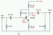
I breadboarded a very basic Common Emitter voltage gain stage as seen in the diagram below and the results are confusing to say the least.
The steady state (Q point) voltage readings (shown in red) seem reasonable, yet this circuit does not behave as I would expect when an audio (AC) signal is applied to the input jack. For example, when I plug an MP3 player into the input jack with a signal level of approximately 0.050 mV AC RMS, the output jack signal measures only about 0.040 mv AC RMS. (Note that these signal levels were measured with nothing more than a cheap Digital Multi-meter).
While I don't have a real signal generator or oscilloscope to run accurate tests, when I connect the output jack of this circuit to an auxiliary input on my Yamaha integrated SS amplifier, the results I hear through my loudspeakers seem to verify what I can read off my DMM. That is to say that the sound level out of the loudspeakers when the Common Emitter stage is in the signal path is less than when I connect the MP3 player directly into the Yamaha.
I'm trying to learn about basic amplifier circuits by trying this very crude circuit as a first step and I realize that it's biasing technique and high output impedance are far from ideal, but a guy's got to start somewhere.
Any feedback on why I'm seeing what I'm seeing will be much appreciated.
Attachments
Typo
This should read as 50 mV on input jack and 40 mV on output jack.
Sorry about that.
For example, when I plug an MP3 player into the input jack with a signal level of approximately 0.050 mV AC RMS, the output jack signal measures only about 0.040 mv AC RMS. appreciated.
This should read as 50 mV on input jack and 40 mV on output jack.
Sorry about that.
Hello Andrew,
Well this circuit sure acts more like a buffer than an amplifier. If I understand the theory correctly, R2 does provide bias to the transistor as well as some negative feedback for thermal stability, yet not so much feedback as to negate any decent voltage gain. I was expecting to see a gain equal to approximately - R3/R4 (-10K/1K = -10)
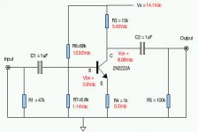
Just for the heck of it I removed R2 and replaced it with a more traditional bias circuit as seen in the diagram below. As expected, the steady state DC voltages remained about the same as before. Unfortunately, the final results were the same when I applied an audio signal to the input as well (ie. no output voltage gain, just a bit of attenuation instead).
I'm so confused!
Well this circuit sure acts more like a buffer than an amplifier. If I understand the theory correctly, R2 does provide bias to the transistor as well as some negative feedback for thermal stability, yet not so much feedback as to negate any decent voltage gain. I was expecting to see a gain equal to approximately - R3/R4 (-10K/1K = -10)
Just for the heck of it I removed R2 and replaced it with a more traditional bias circuit as seen in the diagram below. As expected, the steady state DC voltages remained about the same as before. Unfortunately, the final results were the same when I applied an audio signal to the input as well (ie. no output voltage gain, just a bit of attenuation instead).
I'm so confused!
Attachments
Hello Mooly,
Yes, a scope would be nice. Someday maybe.
Yes, I expected impedance matching to be an issue. In fact, when I started out I had a second 2N2222A wired up as an emitter-follower in the circuit and the performance was the same. So I decided to remove the emitter-follower portion to isolate the problem that I'm seeing now with this simplified circuit.
The audio source is a little Sansa MP3 player that normally drives cheap headphones just fine. The input impedance to my Yamaha amp is specified as being 47K Ohms.
As I said in the beginning, I'm not expecting stellar performance from this experiment, but I was hoping to see some modest amount of voltage gain from my little common-emitter circuit. It seems like I need to sort this out before I explore more sophisticated audio circuits.

Hello Mooly,
Thanks for checking back.
Yes, everything is behaving well as far as I can tell. My ears confirm the AC measurements from my DMM. Plenty of gain now plus no distortion that I can hear.
With the MP3 player connected directly into my Yamaha amp requires that the MP3 player be set to maximum volume and the Yamaha volume dial set between 1 O'clock to 2 O'clock to get a decent listening level.
Inserting this little common-emitter circuit into the path, I can lower the output of the MP3 player to 50 percent and set the Yamaha volume knob back to 9 O'clock to get the same sound level.
Again, thank you for all the assistance.
Best regards,
Obe1
Hello Mooly,
OpAmps? Oh my!
I had 1 chance in 6 to get this 3 terminal device wired up right the first time and I managed to mess that up. These OpAmp things appear to have 8 (or more) terminals, so that reduces my chances for success down to less than 1 in 40,000. No thanks. I'm not that skilled or lucky enough to pull that off.
As for what's next: Well I would like to add back that emitter-follower to lower the output impedance of the design to see what that does. Guess I better go shopping for another transistor since I fried all the ones I had. On second thought, maybe I better buy at least 6 more.
Adding an emmiter follower is a good idea... and good for learning.
You could try a simple 2 stage amp using an npn and a pnp device. Plenty of connection possibilites with that one
OpAmp are great for learning too... you only need a TL071 or even a 741 to begin.
If you can pick up a cheap 'scope and generator then you wil have fun
You could try a simple 2 stage amp using an npn and a pnp device. Plenty of connection possibilites with that one
OpAmp are great for learning too... you only need a TL071 or even a 741 to begin.
If you can pick up a cheap 'scope and generator then you wil have fun
Hello Mooly,
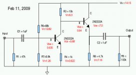
Well I went ahead and added the emitter-follower stage as seen in the attached sketch. Again, everything appears to work fine, although my ears detected a slight loss in overall gain (yet I think that was to be expected).
Thanks for the suggestions on other things to try. I see that TL071 OpAmp you suggested has a J-FET input circuit. This intrigues me as I was reading that J-FETs replicate some of the sonic qualities of vacuum tubes due to their transconductance. As I continued to read, I was a bit intimidated by the fact that individual J-FETs means fiddling around to get them to match. Do TL071's minimize having to stress over mis-matched devices?
Best regards,
Obe1
Attachments
It's good you are trying things out. tbh I wouldn't have expected the gain to be noticeably different with a follower (not audibly so)... and certainly not lower as it "helps" the first stage by isolating it from the load. The voltage gain of a follower is slightly less than 1 (unity) but I'm surprised it's audible. Connections OK
This is where the scope comes in You can see what's happening.
A TL071 is a great way to experiment. Sonically it's excellent... even today. All you need is a couple of 9 volt batteries to get started and a few resistors etc.
This is where the scope comes in
You can see what's happening. A TL071 is a great way to experiment. Sonically it's excellent... even today. All you need is a couple of 9 volt batteries to get started and a few resistors etc.
You asked about it being a JFET input.
One of the main advantages is that FET input stages draw no input current at DC, and that helps with the design of "low offset" amplifiers. Opamps using transistor front ends (Bi Polar junction transistor or bjt's) need the circuitry designing carefully to minimise this effect.
That's all a long way down the line though... any will be good for you to experimant with.
Some of the best opamps have fantastic performance if used correctly and I personally favour some of the FET designs such as the OPA604.
And all the legs are numbered
Hi Mooly,
You're right about using the proper test equipment as my old ears are far from being precise.
I do plan to play around more with these discrete devices before jumping on the OpAmp bandwagon. With that said, It's nice learn that OpAmps like the TL071/072 can function decently of a pair of batteries.
I've tried to follow some of the threads where you were helping people with some very sophisticated OpAmp power supplies and it just seemed overwhelming for a device that's supposed to have excellent PSRR and low power consumption.
Thanks again for all you help and suggestions!
Why not see if you can design your circuit above using a TL071.
Hint... your discrete circuit above "inverts" the phase of the signal by 180 degrees.
or you could use the opamp to ensure the signal is not inverted as it's amplified.
Golden rule for opamp design when using feedback (i.e 99% of the time)... the output will do whatever is required to keep the difference in voltage between the inverting and non inverting inputs at zero
Have fun... try it
- Status
- This old topic is closed. If you want to reopen this topic, contact a moderator using the "Report Post" button.
- Home
- Source & Line
- Analog Line Level
- Basic Common Emitter Amp Help