TR2 base current is determined really by the gain of the transistor, but is pretty small. So with no R4 the bias calculation works out OK.
As R4 is introduced, the base bias current for TR2 is still essentially the same, but the extra current flowing through R4 (0.6ish/R4) is "added" to the collector current flowing from TR2, and all this flows to ground via R6.
So that "extra" current is lifting the emitter of TR1... and the effect of that is to reduce the maximum available output at the collector or TR2.
With R4 at the low value of 180 ohms, the DC voltage at the collector of TR2 has to be set to around 9 volts DC by the bias network for maximum undistorted output. This is because the emitter of TR1 is already at nearly 4 volts DC.
It's very much a balancing act... if you could see it on the 'scope it would make more sense in the way that the bias affects not just the obvious "clipping" level, but how it affects the distortion too.
Even on a scope, at low values of R4 and higher outputs the distortion (not clipping) becomes apparent in the lower part of the waveform.
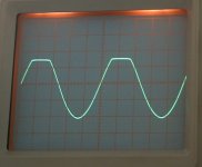
Last two shots showing the distortion.
First one shows the amp isn't "hard clipping" as such, but by altering the bias as in the second that actually gives more "usable undistorted output"
Very difficult to explain 🙂 Get a 'scope 😉 lol
First one shows the amp isn't "hard clipping" as such, but by altering the bias as in the second that actually gives more "usable undistorted output"
Very difficult to explain 🙂 Get a 'scope 😉 lol
Attachments

Hello Mooly,
Very interesting. Thanks for the scope photos.
Please clarify: 1) You started with no R4 and got best performance, 2) then went to R4 equals 470 Ohms and got reduced performance, and 3) finally to R4 equals 180 Ohms for worst performance. Did you mean 47 Ohms not 470 Ohms?
Also, what make & model of scope are you using and what scope would you recommend for a Noob like myself?
Obe1
Last edited:
No R4 gives the highest available output swing. The gain of the circuit is unaffected by all this.
R4 at 470 ohms reduces the available output slightly, but the performance overall is better.
R4 at 180 ohms would give the best high frequency performance... much much higher than is needed for audio.
So as R4 is lowered the available output drops (not good), but bandwidth increases (good). So it's a matter of compromise, and designing for the intended application and gain etc.
The example I scribbled down was just to show the two transistor topology... if you have a very specific application in mind, we can design it much better.
Oscilloscope... mines a 100Mhz Dual Channel, Dual timebase that allows you to expand and view minute portions of a waveform, one on Ebay actually,
HUNG CHANG 5510 OSCILLOSCOPE 100 MHz 3 CHANNEL on eBay (end time 04-Mar-10 05:02:57 GMT)
What you want is an Analogue scope (like mine) definitely not a digital sampling one, or one with an LCD screen. You want the normal CRT type display. Anything over 20Mhz bandwidth, preferably dual channel.
HUNG CHANG 5510 OSCILLOSCOPE 100 MHz 3 CHANNEL on eBay (end time 04-Mar-10 05:02:57 GMT)
What you want is an Analogue scope (like mine) definitely not a digital sampling one, or one with an LCD screen. You want the normal CRT type display. Anything over 20Mhz bandwidth, preferably dual channel.
An oscilloscope thread I remembered,
http://www.diyaudio.com/forums/solid-state/126259-oscilloscope-debugging-audio-signals.html
Some 'scope traces working on audio,
http://www.diyaudio.com/forums/solid-state/126370-oscillograms-testing-why-layout-matters.html
And on OpAmps starting at post #1017. The picture in post 1019 shows how the 'scope can "zoom in" on a portion of the waveform. The dual timebase would allow other traces at different timebase speeds to be displayed all at the same time... not just two channels in the normal sense.
http://www.diyaudio.com/forums/chip-amps/154106-best-sounding-audio-integrated-opamps-51.html
Wow! that is a fine price for a 100MHz scope, assuming it is calibrated and in working order. I bought my 30MHz scope new, but if I had had an extra $500 to spend on it I would have bought the 100MHz one.🙄
Hi Mooly,
Thanks for all the o-scope material. I'll need a few days to absorb all that good stuff.
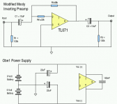
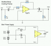
FYI: I purchased a TL071 opamp today and plan on using the following schematic as my first test circuit. As you can see, it is based on your non-inverting design along with my own super sophisticated power supply.
Best regards,
Obe1
Thanks for all the o-scope material. I'll need a few days to absorb all that good stuff.
FYI: I purchased a TL071 opamp today and plan on using the following schematic as my first test circuit. As you can see, it is based on your non-inverting design along with my own super sophisticated power supply.
Best regards,
Obe1
Attachments
You will like playing with OpAmps.
The circuit above wants a little "re arrangement" before it will work 🙂 Rf must go from pin 6 (the output), to pin 2 (inverting input). Everything else is correct.
The thing that may appear strange at first is that you can not "measure" any signal at pin 2.
Can you see why ?
If you applied (for example) plus 1 volt DC to the input (with C1 shorted out of course) can you see what the output will go to and why that appears to give no voltage on pin 2.
PSU is fine (check the battery symbols... 😉)
Hi Mooly,
Thanks for checking my schematic. I drew it right on paper, but wrong on my computer. Regardless, I need to fix it.
As to why I won't measure a voltage at pin 2: The answer can be found in your earlier post (as follows):
Thanks,
Obe1
Thanks for checking my schematic. I drew it right on paper, but wrong on my computer. Regardless, I need to fix it.
As to why I won't measure a voltage at pin 2: The answer can be found in your earlier post (as follows):
"Golden rule for opamp design when using feedback (i.e 99% of the time)... the output will do whatever is required to keep the difference in voltage between the inverting and non inverting inputs at zero"
Question: How close to the plus(+) and minus(-) rails of the power supply need to be? I ask, because I don't think I can count on two batteries staying in voltage sync over time.
Thanks,
Obe1
😉 That's it.
Batteries and PSU... not a problem. It doesn't matter if you have 20 volts on pin 7 and -5 on pin 4 as long as you stay within the max rating for the device which is 36 volts from memory.
However... if you did as in that example then the output would clip assymetrically of course. So no problem with batteries at all and unequal voltages.
On a practical level you can't connect them at the same time so you will get a huge "offset" untill both are connected (switch on thump). So have the volume turned down as you connect and reconnect etc
Side By Side - Round One
Hello Mooly and friends,
This afternoon had got a chance to run a side by side test of the following circuits:
Bye for now.
Hello Mooly and friends,
This afternoon had got a chance to run a side by side test of the following circuits:
Circuit A: This is my common-emitter / emitter follower circuit using a pair of 2N2222A (NPN) transistors.
Circuit B: This circuit uses a single TL071 opamp wired-up pretty much as shown in Post #71. The only difference is I had increase the value of resistor "Rf" from 68K to 220K, as the volume with 68k was significantly lower than Circuit A (and still falls a bit short even now).
Listing to Circuit A through one channel of my Yamaha amp and Circuit B through the other, the two circuits defiantly have their own sonic character. Both sound good, I just didn't have enough time today to evaluate each Circuits strengths. I really need to tweak to things to eliminate the volume/gain disparity, unfortunately my nearby parts store didn't have an appropriate trim-pot that would have made this much easier. Hey, at least I didn't fry anything this time. 😛Circuit B: This circuit uses a single TL071 opamp wired-up pretty much as shown in Post #71. The only difference is I had increase the value of resistor "Rf" from 68K to 220K, as the volume with 68k was significantly lower than Circuit A (and still falls a bit short even now).
Bye for now.
Last edited:
Which version of the discrete amp were you using ? Was it the one with the LED that had a gain approaching 100 ?
Obe,
I see DC blocking at the output of the Pre-amp.
Do you also have DC blocking at the input of the next stage, the Power-amp?
If you have two series DC blockers, the high pass filter will be at a much higher frequency. You only need one DC blocker between each pair of transmitter and receiver. Try bypassing the DC blocker from the Pre-amp output if you know the receiver already has one fitted. Alternatively short out the lower quality cap that is not required.
Hello all,
Yes Mooly, the discrete amp has the LED. I remember from your scope pictures in Post #42 you mentioned "The gain approaches 100 at low input levels below clipping" and I forgot to ask what you did to get a gain that high. I never imagined it was that high as I designed it. FYI: I'll run some listing test again with a 1K resistor in place of the LED.
Andrew, I honestly don't know if my power amp has DC blocking on it's inputs. I'll see if I can find a schematic.
That begs a question: Is it common practice in commercially built products to exclude a coupling cap on the output of a device (be it a source or preamp, etc.) because they assume that any downstream device will include DC blocking on its inputs?
most pre-amps and sources will have a DC blocker on the output.
Some of them will be a small electrolytic which is not good for quality.
Some will be a small metalised film giving better quality but restricted bass extension.
Some some will be a combination of the above.
Some will be a high quality film and foil of high capacitance that can produce both good quality and good bass extension.
Some will not have a DC blocker, but may have a DC servo, with or without DC detection circuitry and protective muting.
You have the option of choosing what suits your budget and your philosophy.
Hi Obe1, it was using an LED in place of the 1 k resistor that gave such high gain... a very unusual idea 🙂 Go back to the 1 K.
What model is your amp ?
What model is your amp ?
Hi Mooly,
Yes, I will try going back to just the 1k Ohm resistor and see what happens.
Question: In your O-scope photo number 5 in Post #42, the output waveform is clipping hard at the bottom (as you said you were pushing it pretty hard) and the upper half of the waveform (while rounded) does not look exactly sinusoidal. Do you recall if the waveform was fairly sinusoidal before being pushed into hard clipping?
My Yamaha Amp: It's actually a receiver unit, a model R-1000, that I purchased new in 1980. The preamp section has it's own output jacks and the power amp section has it's own input jacks. From a switch on the front panel, you can bridge the pre-amps outputs to the power amps inputs or segregate them from one another completely.
Fairly sinusoidal, yes 🙂 That sounds funny 😉
If you can "see" distortion like that on a scope then in reality it's absolutely horrendous in numerical terms... but some distortion is more pleasing to the ear than others, such as even harmonic distortion.
With a dual trace 'scope you can "overlay" the input and output and compare, but even then once distortion gets below a few percent you will not "see it"
The Yamaha... well that's good as you c an use it as a separate power amp for testing these things. It almost certainly does have a capacitor on it's input as a manufacturer has no idea what someone may try and connect... maybe even an LED preamp 🙂
- Status
- Not open for further replies.
- Home
- Source & Line
- Analog Line Level
- Basic Common Emitter Amp Help