I've looked at a few PCB designs in the last few days and i see various approaches for using two layer boards. is there any "state of the art" way of doing it? for example power tracks on one layer, signal tracks on the other? also i notice there's usually a "flooded" layer for gnd. is it better to flood the bottom or top layer - the one shared with the signal or shared with power? others like phonoclone (VSPS) seem to keep signal ground and power ground seperated.
any general advice would be greatly appreciated.
any general advice would be greatly appreciated.


Two questions came up while working on my version of the p88 PCBs.
1.) Size of output caps. The original article says "The paralleled caps at the output are designed to ensure that the preamp can drive a power amp impedance as low as 22k with an overall response that is about 1dB down at 10Hz". Now i intend to use this pre with my ACA which has an input impedance of 10k. Which modifications can I make on the side of the p88 to make it suitable for driving a 10k input impedance?
2.) i'll use the p88 in the same enclosure with a p06 phono pre. P06 has an 1u / 100k CR output filter and P88 has the same configuration on the input. In my prototype I left out the CR filter at the P06 output and it was fine. Now I'll put a rotary selector switch between p06 and p88. Would it make sense to put the CR filter back in place "in front" of the selector switch or can i still leave it out?
Use this RC high-pass filter calculator:
RC High-pass Filter Design Tool
Iirc, there are two 1uF caps in parallel on the P88 outputs. Which equals 2uF.
2uF and 22k ohms in the calculator gives a cut-off frequency of 3.62 Hz. 1 dB down at 7 Hz.
For 10k ohms, 4.4uF will give you the same cut-off frequency.
RC High-pass Filter Design Tool
Iirc, there are two 1uF caps in parallel on the P88 outputs. Which equals 2uF.
2uF and 22k ohms in the calculator gives a cut-off frequency of 3.62 Hz. 1 dB down at 7 Hz.
For 10k ohms, 4.4uF will give you the same cut-off frequency.
Last edited:
2.) i'll use the p88 in the same enclosure with a p06 phono pre. P06 has an 1u / 100k CR output filter and P88 has the same configuration on the input. In my prototype I left out the CR filter at the P06 output and it was fine. Now I'll put a rotary selector switch between p06 and p88. Would it make sense to put the CR filter back in place "in front" of the selector switch or can i still leave it out?
Why don't you connect the P06 to the P88 as shown in Rod's first illustration:
High Quality Audio Preamp
If you do that, you can still leave out the output filter on the phono pre.
Skrodahl, Thanks for your replies!
1)Regarding the CR filter: Would it be right to assume that the last resistor of the P88 will be in parallel with the input impedance of the following stage? So for the calculation it will be C=2uF and R=100k//22k=18k? That would make for a cutoff frequency of 4,4Hz.
If I now assume an input impedance of 10k it would be C=2uF and R=100k//10k=9k. That would make for a cutoff frequency of 8,8 Hz. I think i would have to raise C1 to 4uF to get Fc back to 4,4 Hz.
I know it only makes a small difference. I'm just curious to understand how it works.
2) Yes, that's how I connect it. The question was if I can still leave out the CR filter at the P06 output if there's a selector switch between P06 and P88 (insted of being connected directly). I guess you answered that with a yes") . thanks!
. thanks!
1)Regarding the CR filter: Would it be right to assume that the last resistor of the P88 will be in parallel with the input impedance of the following stage? So for the calculation it will be C=2uF and R=100k//22k=18k? That would make for a cutoff frequency of 4,4Hz.
If I now assume an input impedance of 10k it would be C=2uF and R=100k//10k=9k. That would make for a cutoff frequency of 8,8 Hz. I think i would have to raise C1 to 4uF to get Fc back to 4,4 Hz.
I know it only makes a small difference. I'm just curious to understand how it works.
2) Yes, that's how I connect it. The question was if I can still leave out the CR filter at the P06 output if there's a selector switch between P06 and P88 (insted of being connected directly). I guess you answered that with a yes
. thanks!You're right to assume that the last resistor of the P88 is in parallel with the input impedance of the following stage. Which is probably why he states that the signal is down 1dB at 10 Hz.
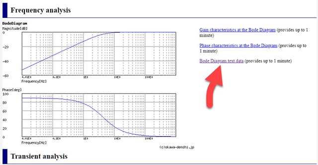
You can get the graph data as text (comma-separated vaules) by clicking on the "Bode Diagram text data" link:
You can get the graph data as text (comma-separated vaules) by clicking on the "Bode Diagram text data" link:
As long as it still has decently low impedance at ~4 MHz, it should be OK. More capacitance may be warranted when the opamps are loaded more heavily, e.g. you'd find more like 220 µF in a headphone driver.
Two things:
1. Boards must be able to integrate in the complete preamp without creating internal ground loops all over the place. I do not think that this is the case with the ground pour connecting everything together. Confirm by drawing out the grounding scheme of a complete unit (power supply + pre + phono).
2. Impedances around the opamps in P88 and P06 are decidedly on the high side and IMHO would give higher noise levels than necessary, especially since OPA2134s and NE5532s are rather good load drivers and not easily impressed by loads even down in the low kOhms. Presumably the values were chosen for the much weaker TL072. I would suggest lowering them by about a factor of 3 for starters, maybe up to 5. (In P06, this would be R2-R7, in P88, R3/4+7/8.) The crux: Any capacitors forming RC time constants have to be increased accordingly, with much fewer values available, so if in doubt select Cs first.
- Home
- Source & Line
- Analog Line Level
- Rod Elliot Project 88 question