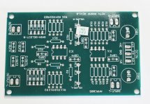
Here it is my new p88 preamp....done and working perfectly....output 14.15 db
Hicoco, nice layout. Can you share pcb layout for self etching?
Please starbender PM, i am traveling right now...my files are in My ICloud drive...will be available not before ThursdayHicoco, nice layout. Can you share pcb layout for self etching?
Use a 10k log pot and change R6L/R6R from 15k to 100k ohms.
Thanks.
I made this circuit on protoboard. It's working fine. I'm using 10k log potentiometer, article mentions that this preamp uses linear pot with fake log resistors. Do I need to remove these resistors from protoboard if I decided to use log potentiometer?
If so, which one is it? 15k?
With 10k log pot use schematic from post 30.
The schematic in post #30 is correct if
Otherwise, use the 10k log pot and replace R6L/R6R with 100k ohms.
- You have a 10k ohms log pot
- You omit the balance pot
Otherwise, use the 10k log pot and replace R6L/R6R with 100k ohms.

Would you please change the title to correctly spell the name? It is Elliott, double 'l' and double 't'.
If balance (and volume) pot is not used my schematic must be used. 15k resistor is for fake log pot used in original ESP schematic. Also, 1k5 must be replaced with 47-100R.
Hi Ivan,
In this reply you said 'if no balance and volume pot'. I'm going to use 10k log for volume, without balance pot. Do I still need to replace r5 to 50-100ohm? Or should I only replace 15k to 100k? Other than that, I see that some resistor values are different than original 88 schematic. Can you explain why is this necessary?
Thanks
If you use 10k log pot without balance pot than my schematic from post 30 should be used. Explanation is in this thread, you should read all 19 pages or simply use post 30 schematic.

I etched another pcb and used resistor values from post 30 schematic.
I'm sure it will be ok. In the meantime I'm using protoboard preamp to test and it seems it's pretty good sounding.
I made B1 and BA3 preamp before this one. I used B1 for almost two years and another two years I used BA3 preamp. Both of them is driving pass F5 clone.
As you know F5 gain is pretty low and it needs a sensitive speakers to shine. I'm using 4 ohm 86dB speakers right now and F5 with added gain from BA3 cannot feed enough juice to these speakers.
I always had distance to opamp base preamps and I always thought it cannot be better than any discrete design. But this little thing is impressive as it is..
I tried NE5532 and OPA2134 so far. I'm planning to try OPA2604 and old jfet input type opamps.
Anyone tried any other opamp with this project?
If so, can you please share your experience?
Thanks..
I tried several opamps with P88 but I prefer bipolar opamps over j-fets. I tried 4558, LM4562, OPA2134 and NJM2114. I use NJM2114 but it will be difficult to find it. I recommend that you try LM4562.
I tried several opamps with P88 but I prefer bipolar opamps over j-fets. I tried 4558, LM4562, OPA2134 and NJM2114. I use NJM2114 but it will be difficult to find it. I recommend that you try LM4562.
I removed lots of old opamps from broken cd players, i think i had njm2114. Will try those.
Thanks.
I was planning on posting a summary of possible resistor / potentiometer combinations that people have used successfully. I hope I'll have time to do it in the next few days...
Let's give this thread an update. I just found a rather new P88 projects on the web and I'd like to share it:
Rod Elliott ESP P88 Pre-amplifier – (mis) Adventures in Hi-Fi
nicely done.
Rod Elliott ESP P88 Pre-amplifier – (mis) Adventures in Hi-Fi
nicely done.
Seems I'm the only one in this thread now :-(
I'm in the process of getting started with EasyEDA to make my own PCBs for this pre. I'd need some general advice for PBC layout for opamp based amps. Can someone point me in the right direction or give me some advice? For Example:
1) track width for signal / power
2) general advice for routing signal and power
3) general advice for gnd plane / pour on the pcb
I know one should keep transformers away from audio circuits - what about rectifiers? Say I power the pre from an AC wall wart and have the rectifier / dual power supply in the chassis. Should that be kept away from the audio circuit?
Yes.
As you mention, the transformer is the biggest noise source, but there is also ringing and noise in the rectification.
A properly designed snubber will make a large difference in radiated noise. Mark Johnson did a very good article in Linear Audio about this.
As you mention, the transformer is the biggest noise source, but there is also ringing and noise in the rectification.
A properly designed snubber will make a large difference in radiated noise. Mark Johnson did a very good article in Linear Audio about this.
Thanks, i'll read up on the snubber topic. Should the rectification also be physically seperated (shielded, kept at distance) from the amplifier circuit?
Regarding the PCB layout: What are the recommended track widths for power and signal?Can Signal and power cross or is this to be avoided?
Regarding the PCB layout: What are the recommended track widths for power and signal?Can Signal and power cross or is this to be avoided?

- Home
- Source & Line
- Analog Line Level
- Rod Elliot Project 88 question