I think there some things regarding grounding that need to be agreed upon.
1: Is our ground connected to the chassis, which is basically a huge antenna unless connected to earth ground? Some houses, mine included, have no ground connection! So perhaps we should treat the chassis as an RF shield rather than absorber. Does someone have experience to offer?
2: How are our signal ground and earth ground isolated, or are they at all?
We need to come up with our grounding scheme. Then we can decide whether we need virtual earth and how to implement it.
This is what I suggest:
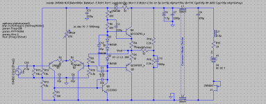
1: Signal ground connected to negative rail.
2: Power ground connected to capacitive virtual earth as in schematic. (I deleted the top capacitor in the schematic since it improves PSRR)
I don't know if signal ground and power ground being connected is a problem for a headphone amp. I see nothing wrong with this. I think we could still get better PSRR if we removed decoupling from the input and made it so that it followed the virtual earth.
In any case I like my virtual earth solution better than the EF virtual eartth because it has lower impedance and is more cost effective, and think it should be used if we decide on a virtual earth grounding scheme.
PS. We should hold an official vote, we really should (possibly through the poll system?). Things to include: relay-switches, multiple headphone outputs, multiple headphone impedances, onboard or outboard supply, etc. I'm sure there are plenty of silent viewers who would vote.
Carlos, that is a great schematic. What program do you use?
- keantoken
1: Is our ground connected to the chassis, which is basically a huge antenna unless connected to earth ground? Some houses, mine included, have no ground connection! So perhaps we should treat the chassis as an RF shield rather than absorber. Does someone have experience to offer?
2: How are our signal ground and earth ground isolated, or are they at all?
We need to come up with our grounding scheme. Then we can decide whether we need virtual earth and how to implement it.
This is what I suggest:
1: Signal ground connected to negative rail.
2: Power ground connected to capacitive virtual earth as in schematic. (I deleted the top capacitor in the schematic since it improves PSRR)
I don't know if signal ground and power ground being connected is a problem for a headphone amp. I see nothing wrong with this. I think we could still get better PSRR if we removed decoupling from the input and made it so that it followed the virtual earth.
In any case I like my virtual earth solution better than the EF virtual eartth because it has lower impedance and is more cost effective, and think it should be used if we decide on a virtual earth grounding scheme.
PS. We should hold an official vote, we really should (possibly through the poll system?). Things to include: relay-switches, multiple headphone outputs, multiple headphone impedances, onboard or outboard supply, etc. I'm sure there are plenty of silent viewers who would vote.
Carlos, that is a great schematic. What program do you use?
- keantoken
Attachments
Last edited:

Hi KT,
I would be quite OK to connect virtual ground to chassis but NOT to IEC ground. This would also scotch any RF if it is induced.
You could join signal and power ground, but keep IEC ground from the power socket connected only to the chassis.
I will go with Nico's suggestion, KT, because it has been used before with great success and the transistor virtual earth also offers a DC as well as an AC path which has to be good for bias currents.
Both transistors can be TO126 BD139/BD140, very cheap, while the complexity is higher, it's a belt and braces approach and covers all current bases.
You should have a cap on both VE resistors, not just one, and the signal and power earth could then be taken off the negative rail and placed on the centre, Virtual Earth as originally suggested. This will deliver the current nulling for very quiet noise outcome, and ensure that there is no asymmetrical switch on pulse.
I do not believe a vote is appropriate; we are seeking the right answer, and truth is not always amenable to a vote! In any event, I'm knackered, so my answer is short.
Cheers,
Hugh
1: Is our ground connected to the chassis, which is basically a huge antenna unless connected to earth ground? Some houses, mine included, have no ground connection! So perhaps we should treat the chassis as an RF shield rather than absorber. Does someone have experience to offer?
I would be quite OK to connect virtual ground to chassis but NOT to IEC ground. This would also scotch any RF if it is induced.
2: How are our signal ground and earth ground isolated, or are they at all?
You could join signal and power ground, but keep IEC ground from the power socket connected only to the chassis.
This is what I suggest:
1: Signal ground connected to negative rail.
2: Power ground connected to capacitive virtual earth as in schematic. (I deleted the top capacitor in the schematic since it improves PSRR)
I don't know if signal ground and power ground being connected is a problem for a headphone amp. I see nothing wrong with this. I think we could still get better PSRR if we removed decoupling from the input and made it so that it followed the virtual earth.
In any case I like my virtual earth solution better than the EF virtual eartth because it has lower impedance and is more cost effective, and think it should be used if we decide on a virtual earth grounding scheme.
I will go with Nico's suggestion, KT, because it has been used before with great success and the transistor virtual earth also offers a DC as well as an AC path which has to be good for bias currents.
Both transistors can be TO126 BD139/BD140, very cheap, while the complexity is higher, it's a belt and braces approach and covers all current bases.
You should have a cap on both VE resistors, not just one, and the signal and power earth could then be taken off the negative rail and placed on the centre, Virtual Earth as originally suggested. This will deliver the current nulling for very quiet noise outcome, and ensure that there is no asymmetrical switch on pulse.
I do not believe a vote is appropriate; we are seeking the right answer, and truth is not always amenable to a vote! In any event, I'm knackered, so my answer is short.
Cheers,
Hugh
Last edited:
So your reasoning is that the socket ground is polluted with all sort of garbage? I was wondering why most plug-ins only have 2 prongs...
You are right about voting... In this case it should be fine to bring up a list of things to ask you about, and if anyone has a reasonable argument changes will be made if necessary. I won't have time until 4:00 (GMT-6), but someone will have to read through posts a few or more pages back and write up a list.
I'm not sure whether this is significant:
What does it matter that we connect chassis to either power ground or signal ground? We could also connect the chassis to the positive rail, but what affect would this have on the circuit, or is it significant at all?
- keantoken
Hi KT,
I actually thought Carlos was lurking in the shadows somewhere") not sharing his thoughts. (I am just kidding, I wanted to see your response)
not sharing his thoughts. (I am just kidding, I wanted to see your response)
Anyway, the program that I use for schematic capture and PCB design is called Easy-PC from No.1 Systems (Number One Systems :: PCB CAD Software :: Home of Easy-PC PCB Design)
And I use MicroCAP9 (Main Redirect) for simulations.
Hugh is right regarding the voting, I support voting for specific features but voting on how Hugh should design the circuit is not an option, it his his call.
Kind regards
Nico
I actually thought Carlos was lurking in the shadows somewhere
not sharing his thoughts. (I am just kidding, I wanted to see your response)Anyway, the program that I use for schematic capture and PCB design is called Easy-PC from No.1 Systems (Number One Systems :: PCB CAD Software :: Home of Easy-PC PCB Design)
And I use MicroCAP9 (Main Redirect) for simulations.
Hugh is right regarding the voting, I support voting for specific features but voting on how Hugh should design the circuit is not an option, it his his call.
Kind regards
Nico
Hi Garterh,
sorry for being a little pushy on the issues at hand but I would like to get started before I get too old. There is still a lot of work to be done. I think the issues are features really.
One could also make the features off-board as it just requires wiring additions as long as the board is flexible enough to attach these extras onto. These are the things I have picked up reading through all 49 pages again and I urge all to submit anything I am missing.
1) Line out
2) Crossfeed (switchable and adjustable)
3) Multiple output (two sockets)
4) Selectable series output resistors (120 Ohm & 10 Ohm)
5) Bootstrap take-off point at output (as per Hugh's amplifiers)
6) Bootstrap take-off point at emitter (as per KT)
7) Virtual earth (Single rail supply)
8) Spilt supply (CT transformer)
9) Single rail supply on board
10) Wall wart 24V regulated
11) discreet regulator (as per Hugh's circuit)
12) Chip regulator (LM317)
13) separate regulators for each channel
14) CMC coil (not as small as you think ref AndrewT or transformers as per Hugh)
15) Single PCB contains all components
16) Amplifier PCB and PSU PCB separate (I am not sure about snap-off dependson PSU size)
17) Battery operated
18) Polyfuses in supply line for protecting the cans against failure or over drive
19) Muting switch
20) Ipod input
21) Tone controls
Kind regards
Nico
I would like to draw your attention to a snap off PSU board, it seems that this would be far bigger than the actual amp.
The snap off idea was good for those who were interested in making their own power supply.
But I am not convinced that we should make everyone pay for a power supply section if this is going to be binned. Consider this while making decisions. The other option is that we stick with whatever Hugh decides and the PSU is not snap-off but compulsory - I like this word actually.
OK, Folks, new day, fresh approach. Thanks to Nico for the list. Here it is, my responses in capital letters (that is, I'm shouting, argument by decibel!):
1) Line out YES
2) Crossfeed (switchable and adjustable) YES
3) Multiple output (two sockets) YES
4) Selectable series output resistors (120 Ohm & 10 Ohm) YES
5) Bootstrap take-off point at output (as per Hugh's amplifiers) NO
6) Bootstrap take-off point at emitter (as per KT) YES
7) Virtual earth (Single rail supply) YES, WITH TRANSISTOR DRIVE FOR VE
8) Spilt supply (CT transformer) NO
9) Single rail supply on board NO
10) Wall wart 24V regulated YES, THOUGH 24VAC NOT REGULATED
11) discreet regulator (as per Hugh's circuit) ONE LM317 FOR BOTH CHANNELS ON THE PCB
12) Chip regulator (LM317) YES, ON THE PCB
13) separate regulators for each channel NO
14) CMC coil (not as small as you think ref AndrewT or transformers as per Hugh) YES, USING LOW TENSION SECONDARIES OFF A SMALL PCB MAINS TRAFO, PRIMARY UNUSED, AS ORIGINAL DESIGN
15) Single PCB contains all components YES
16) Amplifier PCB and PSU PCB separate (I am not sure about snap-off dependson PSU size) NO, ALL ON THE ONE BOARD
17) Battery operated NO
18) Polyfuses in supply line for protecting the cans against failure or over drive NO
19) Muting switch YES
20) Ipod input YES
21) Tone controls YES (WITH SOME MISGIVING BUT A NICE FEATURE)
This is to be the format. I am not prepared to deviate from this under any circumstances because this is an Aspen HP amp and I am ensuring we move forward with the design and I can deliver something I think people want, and which will enhance Aspen's brand. We have agonised over this long enough, and Nico is dead right, we need to nail it down - in truth before both of us get too old........
KT, don't be too concerned about earthing. It's something can be done relatively easily by connecting or disconnecting and trying different approaches. It is important to keep IEC ground, chassis, power and signal ground all separate, so that we can connect and disconnect at will. My confidence lies with connecting IEC ground only to chassis, but signal ground to virtual ground and power ground. You are right, IEC ground can be quite noisy, particularly in industrial areas.
Hope this focusses our direction,
Cheers,
Hugh
I agree with only the safety ground to the chassis, we will have the least interference problems but comply with safety standards.
Hugh you may want to specify your transistors as well, then that is out of the way. I am convinced that this is of sound design as it stands.
Gareth can you make a spread sheet of the features and the just mark +1 for yes and -1 for no in the different columns containing the guys comments. A zero is I don't know and is not a decision. so +1 and -1 is compulsory.
Do not add Hugh's comments to the row. You only use his comment as a VETO in other words if the sum of the comments in that row is zero, or indecisive.
When we do the front panel layout we will follow a similar approach.
This way you can sum the rows and get their weighting per feature.
Gareth,
I suggest you post your e-mail address so the guys can send their votes to you and you can post the spreadsheet here without naming anyone just the +1 and -1 without Hugh's score this way we can see the trend and only use Hugh's score when there is a no decision. Hugh I hope you don't mind complying with this.
Guys, I think we are going to knock together a good product and I would like Hugh to retain the IP for this HP-amp in its entirety for commercial purposes - even if there was a lot of positive input from all of us. After-all he has to put bread on the table.
My turn to sleep, cheers guys see you all later.
Nico
Final request, all you lurkers that has said noting so far, please do your bit as well, it would be an excellent marketing tool for Hugh to see the general trend and give an indication if you would be interested in PCBs on the same e-mail at least Hugh would be able to get volume quotes. It would be pointless doing one or two PCBs, if this is the case then you guys will have to do your own from the Gerber plots or pay exorbitant amounts to have it done.
Nico
Nico
Thanks Nico,
The VAS is Toshiba 2SC3423, bias diodes 1N4148, outputs 2SC4793/2SA1837.
I have decided to go for BC557B (or C) for the input devices. This is a 300MHz device with very high gain and very low noise. It's rated to 45V Vceo and 100mA cont, more than enough. It is optimsed for 1mA-20mA collector current and widely available.
I think that's enough to get started on the pcb?
Cheers,
Hugh
Final request, all you lurkers that has said noting so far, please do your bit as well, it would be an excellent marketing tool for Hugh to see the general trend and give an indication if you would be interested in PCBs on the same e-mail at least Hugh would be able to get volume quotes. It would be pointless doing one or two PCBs, if this is the case then you guys will have to do your own from the Gerber plots or pay exorbitant amounts to have it done.
Nico
It looks to me like 1-4, maybe 10, and 19-21, are features, but would not impact the basic sonics. Do you really want votes on the rest, too? It seems to me that those are technical specifications that would have a sonic impact.
Sheldon
Sheldon,
Good point. Here are the eight significant voting features, the rest are technical parameters now set in stone. This will make it simpler for Gareth to do a spreadsheet (polite request??) and tabulate the results for all to examine:
1 Line out
2 Crossfeed (switchable and adjustable)
3 Multiple output (two sockets)
4 Selectable series output resistors (120 Ohm & 10 Ohm)
5 Wall wart 24V regulated
6 Muting switch
7 Ipod input
8 Tone controls
Hugh
- Home
- More Vendors...
- AKSA
- Aspen Headphone Amp