carpenter said:
I removed those four caps and everything is looking good; in fact, the sine wave looks exactly the same on the simulator. Thanks a bunch for the education.🙂
woodie - I didn't analyzed these circs so thoroughly ( because you fire them almost fast as LL build amps ) but point is -try to construct them with smallest number of caps you can ;
so - in case of mosfet/jfet if you anywhere have CCS ( for biasing ) - then try to tie gates to gnd potential (DC wise) , and let CCS to do what's his role - to bring his side where it needs to be ;
etc .
you didn't answered my question regarding that sole choke ;
Zen Mod said:
you didn't answered my question regarding that sole choke ;
I thought I did in the last couple of post....... #538
Love you like a brother!😀
carpenter said:
I thought I did in the last couple of post....... #538
.......
now you know that I'm 4eye

carpenter said:
....
Love you like a brother!😀
well - you have no choice ........ I'm a peach

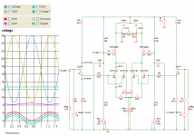
I laid out a version the uses the 2SJ74 jfet at the input. I also paid close attention to aligning current to voltage on the LU1014D ID/VDS graph. Just for the fun of it, I also did the same for the IRFP044N mosfet. It's current is rated at roughly 6 amps to 10 volts (V/D) with a VGS of slightly under 4.5V.
If anyone sees an ugly here or there, please feel free to let me know.
BTW, it takes two LU1014D jfets to deliver enough current to hit the IRFP044N sweet-spot.
I'm not entirely up on the use of the 2SJ74, and can't seem to understand how to graph its parameters. Any help in that dept. would be appreciated. As designed, each 2SJ74 delivers 4.5mA to each LU1014D.
Attachments
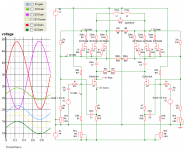
I'm probably over-doing it with the design bit, but this software is a blast to use.
Here's another idea--you know how a little girl can wrap her dad around her little finger? That concept reminds me of what I'm doing with this design. I affectionately think of it as my version of "Daughter of Zen". 😀
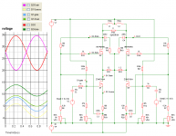
I'm proposing the use of a ZVN3310/IRFP044N cascode arrangement. I may be nuts, but the sim says it will work. It's just strange enough that I'll build this one.
Imagine an itty-bitty ZVN3310 controlling the big brute IRFP044N above. I bias up the IRFP044N separate from the ZVN3310. I don't know if this can be done in reality, but it could sound pretty sweet should it work.
Here's the concept schematic (more fine tuning to come, and yes, I realize that the IRFP044Ns are going to fry at the proposed settings) Water cooling anybody?:
Here's another idea--you know how a little girl can wrap her dad around her little finger? That concept reminds me of what I'm doing with this design. I affectionately think of it as my version of "Daughter of Zen". 😀
I'm proposing the use of a ZVN3310/IRFP044N cascode arrangement. I may be nuts, but the sim says it will work. It's just strange enough that I'll build this one.
Imagine an itty-bitty ZVN3310 controlling the big brute IRFP044N above. I bias up the IRFP044N separate from the ZVN3310. I don't know if this can be done in reality, but it could sound pretty sweet should it work.
Here's the concept schematic (more fine tuning to come, and yes, I realize that the IRFP044Ns are going to fry at the proposed settings) Water cooling anybody?:
Attachments
Hi,
I spent some hour reading this jolly thread. I'm thinking of building me a ZV7-T with some custom wound toroids. www.toroidy.pl can make up to 3 kVA customwound so I wonder if anyone has the opinions of ideal values. I think Magura came up somewhere in the beginning of the thread with that each winding should be at least 80 mH and less then 3 ohm DCR. A 3 kVA toroid would do thet easily of course but I wonder if anyone has opinions om what values to aim for. I guess that a 3 kVA wound like a 2*115 V would end up in the region 1 H, 1 ohm :ish.
Best regards
Staffan
more turns - more stray capacitance yukyuk
keep it at bay - saying that you need entire core covered with wire , so one layer is minimum
sort of gamble - will you go to use 1KW5 , 2KW or 3
whatever you choose - I see no reason to cry later ;
btw. capacitance can be somewhat lowered with connecting small chokes in series with each winding
keep it at bay - saying that you need entire core covered with wire , so one layer is minimum
sort of gamble - will you go to use 1KW5 , 2KW or 3
whatever you choose - I see no reason to cry later ;
btw. capacitance can be somewhat lowered with connecting small chokes in series with each winding
So ordering 3 KVAs with only the primarys wound for 2*115 V would be a fair gamble? The audiogrades will be with epoxy filled centers so I can not unwind it.
yup - just primaries ;
if you can , say that your goal is rather fully covered core than exact number of turns (needed for any voltage )
they don't care - that's just few clicks on machine control panel
if you can , say that your goal is rather fully covered core than exact number of turns (needed for any voltage )
they don't care - that's just few clicks on machine control panel
Well as far as I know the primarys for 2*115 V usually goes in some layers on toroids so it should cover the core all righty.
So you dont think I should go straight on those stuff?
B32526T1476K EPCOS | Mouser
B32678G3476K EPCOS | Mouser
FFB44E0476K AVX | Mouser
/Staffan
B32526T1476K EPCOS | Mouser
B32678G3476K EPCOS | Mouser
FFB44E0476K AVX | Mouser
/Staffan
Hi
I'm on some early projecting here and had a lookie in my closets. I had some 400 VA 2*12 VAC that I could use one per monoblock with dual graetz. Then I could do with dual 25 V caps per rail and RC. Or I also had some 400 VA 2*24 VAC that i could use. Then I need single 50 V caps. What would you prefere here? And what values on the filtercaps per RC?
Best regards
Staffan
- Status
- Not open for further replies.
- Home
- Amplifiers
- Pass Labs
- ZV7-T (transformer)