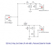
I am building a 2nd Order XO for a 2-Way speaker. I have it pretty much figured out, but I am not sure if I will need a Zobel or not. At this time I have the speakers dialed in at a XO frequency of 520 Hz. I am using an active XO (24dB) and it is the best setting. I would build a 4th order, but simply put, it is too much $. At 520 Hz both drivers are at their flattest impedance curve. For one driver, Markaudio CHR70.3A the rise in impedance starts shortly after, and for the woofer, HiVi M5N, the rise in impedance starts shortly after also. Since, at my XO frequency of 520 Hz my drivers are at their almost flat impedance curve point, do I need a Zobel, or not much needed in this case?
Zobels not required for active xovers (& hardly ever for passive, they're just a cop out for lazy designers...)
Zobels not required for active xovers (& hardly ever for passive, they're just a cop out for lazy designers...)
LOL...So many school of thoughts and so many opinions on the subject, the other day I asked a question regarding a BSC filter for a speaker I built, and there were those that said it is not necessary as the difference can hardly be heard, others that said that it was needed to have a balanced speaker, and others said that if you placed them this way or that way it was needed or not needed.
Anyways, yes I know they are not needed for active XO. Not using them for my active XO, I am building passive XO to be able to use the speakers in different rooms. I am newbie regarding XO building, but have designed and made a few. So, far no complains, but I tend to overthink stuff. The way I have been doing it so far, is take the Impedance of each driver at the XO frequency, as per the manufacturers Impedance Response Curve, and use that Impedance to calculate my XO components. Not 100% sure this is the proper way, I am sure there is more to it, but so far it has worked for me.
Having said that, you would agree that since my drivers are being crossed at their flattest Impedance curve freq. I won't need a Zobel. Correct?
Enclosed is an schematic of the XO.
Attachments
There is. There are many ways to implement an identical crossover using passive components (ie the primary end result is the same), and it depends on how you go about it. In some cases it is easier to use Zobel style compensation. Usually the same filter without, will have slightly different values which can be arrived at through measurement/simulation.I am sure there is more to it,
Baffle step is a more complex situation because it cannot be fixed. It can be arranged and compensated so that it is not a problem. It is basically a physical phenomena that should be accounted for in the design of the speaker.
LOL...So many school of thoughts and so many opinions on the subject, the other day I asked a question regarding a BSC filter for a speaker I built, and there were those that said it is not necessary as the difference can hardly be heard, others that said that it was needed to have a balanced speaker, and others said that if you placed them this way or that way it was needed or not needed.
Anyways, yes I know they are not needed for active XO. Not using them for my active XO, I am building passive XO to be able to use the speakers in different rooms. I am newbie regarding XO building, but have designed and made a few. So, far no complains, but I tend to overthink stuff. The way I have been doing it so far, is take the Impedance of each driver at the XO frequency, as per the manufacturers Impedance Response Curve, and use that Impedance to calculate my XO components. Not 100% sure this is the proper way, I am sure there is more to it, but so far it has worked for me.
Having said that, you would agree that since my drivers are being crossed at their flattest Impedance curve freq. I won't need a Zobel. Correct?
Enclosed is an schematic of the XO.
The Zobel network needs to be directly across the driver's terminals to flatten the impedance of the driver, that will give the LP filter a more constant load. The way you show it won't do anything but add an extra frequency dependent load on the amp.
Mike
The Zobel network needs to be directly across the driver's terminals to flatten the impedance of the driver, that will give the LP filter a more constant load. The way you show it won't do anything but add an extra frequency dependent load on the amp.
Mike
This is what common sense told me, but for some reason a tutorial I was reading
said that the Zobel goes after the XO. But, now thinking about it well, the signal comes from the amp to the drivers, so after the XO would be just before the driver; now makes sense.
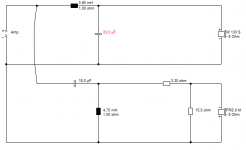
Here is the corrected XO network drawing with Zobel properly placed...Thx
You got it.
Mike
try this in XSim: enter your crossover, note the FR curve, then delete the zobel, & up C3 to ~39uF .... same result
Having said that, you would agree that since my drivers are being crossed
at their flattest Impedance curve freq. I won't need a Zobel. Correct?
The primary function of a Zobel is to shape the FR of the driver
whenever you can't do that with a typical LP filter only. It doesn't
have to flatten the impedance of the voice coil at all, it can be
of values whatever makes you feel that the job is done correctly
and this you achive by measuring or modelling.
Mostly you can get away without one. When there is a FR hump just
before the slope of the low passed response starts to dip down, then
an RC filter (Zobel) may be desired.
Guangui,
There are many true statements. By flattening the impedance of a single driver you can get a more consistent high-pass filter slope for that driver.
There's a hidden secret there only a few guru's know or will share. Tweaking the values of a Zobel you can use it to nudge the phase 180 degree crossing point left or right letting you optimize that independently (within a small range) of the crossover settings and getting near perfect phase matching.
LR4 is never useful unless it is useful. 🙂 That is, I find it a PITA to implement in a passive well, so you really need to want it. Like dating the pretty girl who has a lot of attitude. Make sure you can afford the compromises you'll have to make. 😀
Best,
Erik
I am building a 2nd Order XO for a 2-Way speaker. I have it pretty much figured out, but I am not sure if I will need a Zobel or not. At this time I have the speakers dialed in at a XO frequency of 520 Hz. I am using an active XO (24dB) and it is the best setting. I would build a 4th order, but simply put, it is too much $. At 520 Hz both drivers are at their flattest impedance curve. For one driver, Markaudio CHR70.3A the rise in impedance starts shortly after, and for the woofer, HiVi M5N, the rise in impedance starts shortly after also. Since, at my XO frequency of 520 Hz my drivers are at their almost flat impedance curve point, do I need a Zobel, or not much needed in this case?
try this in XSim: enter your crossover, note the FR curve, then delete the zobel, & up C3 to ~39uF .... same result
Thanks for the tip, will simulate.
Guangui,
There are many true statements. By flattening the impedance of a single driver you can get a more consistent high-pass filter slope for that driver.
There's a hidden secret there only a few guru's know or will share. Tweaking the values of a Zobel you can use it to nudge the phase 180 degree crossing point left or right letting you optimize that independently (within a small range) of the crossover settings and getting near perfect phase matching.
LR4 is never useful unless it is useful. 🙂 That is, I find it a PITA to implement in a passive well, so you really need to want it. Like dating the pretty girl who has a lot of attitude. Make sure you can afford the compromises you'll have to make. 😀
Best,
Erik
Not too fond of LR4, but mainly because of the amount of components, and the increase in budget it takes, which defeats the purpose of my design, which was a bookshelf speaker with good bass response, great sound, and with the advantages a full range driver in an OB can deliver. The sound of this speaker is very open, detailed, has wonderful mids, warm, easy to drive, and useful bass in the mid 50's. I have settled on an LR2 XO, as IMO is the best compromise for this design.

Guys, thanks for all the help. If it helps with anything, and someone wants to have fun doing better modeling than what I do. Design is a hybrid OB bookshelf with HiVi M5N used as woofer in a ported 0.25 cu.ft. enclosure with a 1" dia. x 2" long vent. A full range Markaudio CHR70.3A is used in an open baffle for 520 Hz to 20k Hz. The open baffle for the full range driver is 7-1/2" wide x 16" high, and the pair of speakers is mirror image with the driver's center located at 2-3/4" from the inside edge of the speakers and 2-15/16" from the tope edge of the baffle. Here is a VIDEO for those who may not have seen it in another thread.
Sometimes you can get an LR4 response with just an inductor and an RC, used like Zobel compensation but with different values.
But, would I need to use it in both drivers? Or, just in one of them? Without reading much about it, I guess the idea is to build a Series Notch Filter that will lower the response at XO frequency, artificially creating a slope as to mimic a 4th order. Or, am I wrong?
You are filtering so low (500Hz) that the drivers are effectively flat and resistive.
So second order filters give second order slopes. ie 12dB/octave. Hence negative polarity LR2 when roughly time aligned.
So second order filters give second order slopes. ie 12dB/octave. Hence negative polarity LR2 when roughly time aligned.
It depends what you start with. My point was that fourth order networks are rarely needed, but fourth order responses are not uncommon.
Yes you can often force the response to be similar to something you want using less components, at the expense of the way it behaves out of band and still have a useable response, and it comes down to priorities and compromise. Simulation is a good educator here especially where a target slope can be used in the process (as in the image I posted), even though such a slope is optional.
Yes you can often force the response to be similar to something you want using less components, at the expense of the way it behaves out of band and still have a useable response, and it comes down to priorities and compromise. Simulation is a good educator here especially where a target slope can be used in the process (as in the image I posted), even though such a slope is optional.
You are filtering so low (500Hz) that the drivers are effectively flat and resistive.
So second order filters give second order slopes. ie 12dB/octave. Hence negative polarity LR2 when roughly time aligned.
Thanks, you confirmed what I had modeled with my basic XO knowledge. So, happy for that. Yes, I reversed the polarity of one of the drivers, but not because at the time I knew why it had to be done, but because I have read that with LR2 you have to do it as a rule of thumb. When I connected the speakers to the active XO, they didn't sound right when played with the same phase response, once I pressed the 180D phase reverse button for one of the drivers, the sound totally changed, it became "sweeter", but more importantly much more coherent.
It depends what you start with. My point was that fourth order networks are rarely needed, but fourth order responses are not uncommon.
Yes you can often force the response to be similar to something you want using less components, at the expense of the way it behaves out of band and still have a useable response, and it comes down to priorities and compromise. Simulation is a good educator here especially where a target slope can be used in the process (as in the image I posted), even though such a slope is optional.
Thanks for that explanation. My compromise is to have the best passive XO design I can get within a reasonable budget. Heck, I could go with electro caps, but for the sound I want, and the reason behind the build, MKP's are the way to go; maybe in the near future by-pass them with 0.01uF TFE caps, but that discussion is opening a new can of worms.
If you ensure the response for each driver is correct up to a point where the response should and does find itself significantly down from the main level, say by 24dB, then you should be good.
With regards to the quality of your capacitors, you might find you want to play with the values a bit before you settle on something. I have all the values I need, for example, but I only go out of my way to get good poly caps in some select values. When I'm building a new crossover I'd rather use the best value of electrolytic than a less appropriate value in PP.
Just a side note.. sometimes I can force some value of capacitance to be correct, ie a component that I want to use by fiddling the values of resistor in an L-pad.. provided it suits the amp I'm using.
- Status
- Not open for further replies.
- Home
- Loudspeakers
- Multi-Way
- Zobel XO Question