Physicist, the true pinnacle of Western Empiricism. Knows why we don't own Bose.
Only within limits.
Now if you could tell me why people own Bose on the quantum level.. it ends up in argument of theorists all arguing theirs is the best to get grant money..

Only within limits.
Now if you could tell me why people own Bose on the quantum level.. it ends up in argument of theorists all arguing theirs is the best to get grant money..
I tried measuring why people own Bose stuff... but when I measure it looks like they own Maggies.
So, it's uncertain whether they "can't hear" the difference or it's just a quark of their imagination.
The core rotation and feed rings are separately controlled using an arduino. I program in the pitch of the winding. That video shows me winding with the wire line fit at the core ID. For a DCCT core, I used a pitch that evenly spaced 100 turns around the core.But how does it know? (how far to move the core)
Is there a dial or a cog to set wire gauge?
I also built in the ability to have the ID and OD wire placement lay perfectly vertical, with all the core rotation occurring when the wire is laid on the top or bottom surface. Or have all the core rotation occur ID or OD.
Oh, I used a two ring setup in order to maintain tension on the wire throughout the full feed ring rotation. Many toroid winders use a shuttle, and as the shuttle heads towards the toroid, the wire goes loose. Eventually it goes tight and the wire is pulled to the toroid surface. When I visited the winder manufacturers, I was very unimpressed with the shuttle. Granted, for high speed mass production, it is great. But I needed very tight control of the wire spacing.
John
The power supply engineer needed several gauges of wire wound on the toroid, and a few different patterns. The tight one in the video, a perfect pattern of 100 turns over 360 degrees, and a total anarchy 500 turns on 4 layers over 270 degreed of the toroid.Yes, I see. The wire spacing impressed me. I thought it was a mechanical control!
Learning the arduino was cool, as was the machining on the mill and lathe needed to construct the winder. I had to make fixturing to tap 0-80, up to #2 screws, they are so tiny.. Also, had to figure out how to use a 5 mil (.005 inch) saw blade to cut the machined rings.
I used native code for the arduino, no assembly code involved, so the pop noise every ring rotation was the delay in the code needed to update the display.
George, good to see you made the bridges and verified what Cyril pointed out oh so many years ago. It is really weird seeing reflections within the audio band with tens of feet long cables, no?
Thanks,
John
PS.. recent tools... a wood steamer generator, a glass kiln (refurbished and awaiting K type thermocouples for arduino control of the firing profile) for reforming stained glass into curves, a resin 3-D printer (I really like the resolution despite the small build area, mine is 6 inches by 7 inches. Next, I think I will build a semi-cnc router that can follow a 3-D printed curved surface and cut a vermiculite board to the same shape. I never knew vermiculite could be used for slumping forms in a kiln with temps high enough for glass. I want to go true 3-D with my stained glass projects.. At the moment, fixing a watch gear, amazing how bad everything looks on the lathe at 40 power. Just putting the grinding blade fixture back into the 3 jaw gives an abysmal amount of movement.. Turns out, the 3 mil runout of the 3 jaw is too much for watch gear grinding, so I have to face the holder everytime I re-chuck it. I think I will purchase a USB microscope and use the 29 inch monitor to view the setup and process, the 3-D view is somewhat lacking in real precision due to the two angles of view and the difficulty in placement.
Fun stuff.. cheers.
Alas, had I known you were winding toroids, I might have been able to help.
Nice work George..
My winder in action..
I would have never guessed... so the "loop" is closed around the toroid and then the wire is loaded.
At the end of the winding action, you should have very little wire left on the loop since that will be cut and tossed away, otherwise you could not detach the transformer... sort of like two links in a chain.. the "loop" has to be "cut" so the transformer can be detached.
CLEVER. I would have not thought of it. I kept thinking of somekind of a contraption where the wire loop was carried "around" the transformer core but had no clue how to do that except for a very complex mechanism with a hand off between the top and bottom... the way a human would wind it up.
Thanks. I learned something new today.
I love this coil winder John 
 At whatever freq and at whatever conductors length, electrical phenomena have to be the same
http://www.ivorcatt.co.uk/x726.pdf
“Photons (the field carriers of EM energy) cannot stand still, they can only travel at the
speed determined by the local μ and ε “
George
Ob schwarz ob brown, ich liebe alle frau’n (Nina Hagen’s parody)It is really weird seeing reflections within the audio band with tens of feet long cables, no?
At whatever freq and at whatever conductors length, electrical phenomena have to be the samehttp://www.ivorcatt.co.uk/x726.pdf
“Photons (the field carriers of EM energy) cannot stand still, they can only travel at the
speed determined by the local μ and ε “
George
All, other than possible instability of some amplifiers loaded with long cables (simulated by distributed elements model) that are "open" at the end re high frequencies was found here? I mean if there was any benefit of special winding topologies and techniques found and demonstrated in the audio band, preferably on DBT test basis. Or are we in pure theoretical speculations?
I love this coil winder John
Ob schwarz ob brown, ich liebe alle frau’n (Nina Hagen’s parody)
http://www.ivorcatt.co.uk/x726.pdf
“Photons (the field carriers of EM energy) cannot stand still, they can only travel at the
speed determined by the local μ and ε “
George
George;I would have never guessed... so the "loop" is closed around the toroid and then the wire is loaded.
At the end of the winding action, you should have very little wire left on the loop since that will be cut and tossed away, otherwise you could not detach the transformer... sort of like two links in a chain.. the "loop" has to be "cut" so the transformer can be detached.
CLEVER. I would have not thought of it. I kept thinking of somekind of a contraption where the wire loop was carried "around" the transformer core but had no clue how to do that except for a very complex mechanism with a hand off between the top and bottom... the way a human would wind it up.
Thanks. I learned something new today.
The DCCT measures a DC current flowing through it. It drives a 17 Khz signal through one set of windings on two cores in opposite directions (to cancel the 17Khz and prevent coupling that to the wire being measured). The overall circuit watches for core saturation asymmetry, I think it generates second harmonics and produces an offset signal. There's more, but I'm not sure where IP comes into play so can't give more info. I believe there are some very good pages out there describing the operation. The even spacing seems to have been about accuracy, down in the tens of PPM level.
TonyEE:
Your assessment of operation is accurate.
And yes, it is very clever. I wish I had been the one with the original idea. I copied one I found on youtube, just had to wrestle with scale.
John
Pavel
From my part, only exploring the theory through testing and measurements or repeating the work of others . That is, theorizing if you like.
I am testing the technical parameters at the amp/cable/speaker interaction for my own understanding and I report the abouts here.
So far, amplifier oscillation is the only smocking gun.
The HF termination at the load side seems to be the technically adequate move.
The understanding of the underlying mechanisms, the reason for choosing proper components are the gains of the journey for me.
For members with solid EE background this maybe an unnecessary resources and bandwidth waste.
I understand it and I can accept that. 🙂
John, sorry I experience memory gaps. What is this DCCT and where has it come into our discussion again?
Your description matches a circuit in WW ‘Circuit Ideas’ about a non invasive DC measuring instrument.
I just called a member who has built it (https://www.diyaudio.com/community/members/mkerk.414571/) and he sent me the documentation (attached).
George
Attachments
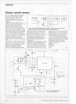
That is the exact mechanism of operation. The second coil, w2, tries to zero the net DC current through the toroid. So if 50 amps are flowing through the single turn of the measured wire, and w2 has 500 turns, the circuit will push 100 milliamps through w2 to zero the net current.For members with solid EE background this maybe an unnecessary resources and bandwidth waste.
I understand it and I can accept that. 🙂
John, sorry I experience memory gaps. What is this DCCT and where has it come into our discussion again?
Your description matches a circuit in WW ‘Circuit Ideas’ about a non invasive DC measuring instrument.
I just called a member who has built it (https://www.diyaudio.com/community/members/mkerk.414571/) and he sent me the documentation (attached).
George
The caveat to that circuit is that the oscillator coil w3 will couple and inject some of the hf signal into the wire being measured. If you double the toroids, lock both w3 coils together by running in series but put one opposite the first, the coupling to the measured wire is reduced to zero.
I only mentioned the DCCT because that is why I built the winder. But using it to wind cores for a bridge would also be fun.
John
John I guess you mean W1The caveat to that circuit is that the oscillator coil w3 will couple and inject some of the hf signal into the wire being measured. If you double the toroids, lock both w3 coils together by running in series but put one opposite the first, the coupling to the measured wire is reduced to zero.
The builder of that instrument has remarked that the circuit is marginary stable. Perhaps what you suggest may be the cure to the oscillation.
George
Pavel
It's always a pleasure for me to see you here and be benefited by your technical contribution.
George
It's always a pleasure for me to see you here and be benefited by your technical contribution.
George
Yes, you are correct. I would have called the tested wire w1, so made that mistake.. Should start the morning with coffee before reading, not the other way around..John I guess you mean W1
The builder of that instrument has remarked that the circuit is marginary stable. Perhaps what you suggest may be the cure to the oscillation.
George
Actually, many of the toroid winders I saw at the vendors were analog. But the use of a shuttle means they can get away with mechanical inaccuracies, whereas very accurate wire placement needed the two ring setup.@Pano, you are such an analog guy 😀
Ah, forgot to mention... I also wanted the ability to modulate the toroid rotation tied to the ring rotation. I programmed four quadrants of ring operation and used four different toroid rotation rates to allow determining where the turns advance in toroid rotation space. For example, have the wire placed on the ID perfectly vertical with no toroid rotation, then just before the wire touches down on the underside, quickly rotate the toroid. That is the point where wire tension keeps the corner stationary. In the end, the final toroid wind design simply used an electronic gearing solution, But the bells and whistles were there should they be needed.
John
Last edited:
So John, next challenge is a solenoid conditioned pendulum clock with coils you wound yourself...
(was it IBM who used to make those amongst others)
(was it IBM who used to make those amongst others)
My grandfather clock, mantel clock, and wooden gear clock are roughly 1 min per day accurate. No need to get really accurate, they are all just decoration and memories of my wife.So John, next challenge is a solenoid conditioned pendulum clock with coils you wound yourself...
(was it IBM who used to make those amongst others)
A guy at work is doing the pendulum in a vacuum solenoid drive thing. However, he is doing it for fun, same as me for my hobbies.
Solenoid winding is easy by hand.. no fancy things there..so where's the fun??
I continue to extend my skills and tools, and quite honestly, all this tool stuff will go to my daughter when I pass, as she is very artistic and tool savvy.
But, I preach to the choir with you and your daughter, no??
jn
My grandfather clock, mantel clock, and wooden gear clock are roughly 1 min per day accurate. No need to get really accurate, they are all just decoration and memories of my wife.
A guy at work is doing the pendulum in a vacuum solenoid drive thing. However, he is doing it for fun, same as me for my hobbies.
Solenoid winding is easy by hand.. no fancy things there..so where's the fun??
I continue to extend my skills and tools, and quite honestly, all this tool stuff will go to my daughter when I pass, as she is very artistic and tool savvy.
But, I preach to the choir with you and your daughter, no??
jn
speaking of clocks and pendulums and intertial measuring units....
I used to work doing avionics for a large military cargo aircraft... uses Inertial Reference Units (IRU) and GPS Aided IRUs, (GIRUs).
Whenever we wanted to test the IRUs and GIRUs... we'd shut off the plane completely, get a tow to move the plane facing in a different direction, power up the plane and wait half an hour for the IRUs and GIRUs to come up with a new solution.
My first go around at that rodeo I asked if it wouldn't be easier to just shift the LRUs ( the electronic boxes, AF parlance ). I was told it took six hours to install and calibrate one of those things, so it was easier to just move the plane around the tarmac.
"1 minute per day"? Jeez, that's about as accurate as a "hundred cubits per forthnight"... we used our IRUs and GIRUs to maintain formation flying within 4000 yards... When you think about it, calculating an aircraft's position and absolute velocity is quite hard. You gotta take into account air speed and actual positioning.. and GPS is only good for a solution per second. So, if you're going fast enough you got to do lots of extrapolation. Thus, in come the IRUs which use inertial gyroscopes (hence the half an hour settling down on power up) and very sensitive electronics to measure the gyros shift based on external forces.
Recall that a gyroscope and a pendulum are related ( just in case you are wondering where all of this is coming from... ever seen a Foucault Pendulum?)
It was a fun job. Even if they issued me those Bose headphones, which actually work quite well.. headphones, microphone, back ground noise isolation, PTT button, etc....
Oh, back in the 80s I worked on a missile's intertial assembly. It was imply awesome. I think they chose me to work on it because I was the only one in our engineering group with an actual degree in Physics and Math ( the rest were EE's ) and I could handle the cosine tables.
Last edited:
I guess Lasers gyros is a breeze.and wait half an hour for the IRUs and GIRUs to come up with a new solution.
Sperry’s electromechanical gyros for B747/B200 required two hours warm up and stabilizing with aircraft in a stable position before ready for transoceanic flight.
George
- Home
- General Interest
- Everything Else
- Zip cord for speaker test