Hi Pavel.
Thank you, I try 🙂
===
Sowter has assigned type number 9846 to the line stage output transformer.
I will add this information to the website.
===
L200 current source temperature tracking circuit schematic now in:
http://www.susan-parker.co.uk/zeus-schematics-1.htm
Best wishes,
Susan.
PMA said:Susan,
your diligence is admirable 😉
BR,
Pavel
Thank you, I try 🙂
===
Sowter has assigned type number 9846 to the line stage output transformer.
I will add this information to the website.
===
L200 current source temperature tracking circuit schematic now in:
http://www.susan-parker.co.uk/zeus-schematics-1.htm
Best wishes,
Susan.
Website Updates
Dear All,
Added Sowter transformer info to Line Driver page:
http://www.susan-parker.co.uk/zeus-line-driver-1.htm
Updated schematic and added some notes to the toroid amp page:
http://www.susan-parker.co.uk/zeus-toroid-amp-1.htm
as there might be some issues when using a large VA input transformer under overdrive conditions which could destroy the zener protection part and then exceed the mosfet Vgs rating.
I have added a further resistor between the transformer winding and the zener for each leg, and increased the zeners rating to 5 watts.
With the small Sowter type input transformer I was relying on the resistance of the windings, but for transformers over 15VA this may not be high enough.
I have also shown the tenth ohm current measuring resistor which I use for setting the mosfet quiescent Vbias current.
I hope this helps.
Best wishes,
Susan.
Hi Susan,
There have been three reasons why I have never contemplated constructing your amplifier;
1. I am not sufficiently up to date with current Mosfets.
2. I do not like output transformers in audio amplifiers.
3. I don't normally use 100W-8R, but I do want that sort of capability for dynamic reserve.
My own high power experimental class-AABB agenda turned out to be sonically flawed due to the biasing mechanism within the JLH class-A topology causing problems for my non-linear output stage, but I have never stopped thinking about your design.
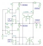
For (1) above I must rely upon the advice of others, but for (2) and (3) I offer the attached solution. My simulator does not offer a three winding transformer, so I have been obliged to draw two separate transformers and parallel the primaries. The secondaries need to be separate.
With suitable Mosfets in this circuit, there is no reason why your circuit cannot now be constructed to *any* desired output power as long as the input transformer has sufficient step-up ratio and the pre-amplifier a low impedance driving capability, say not more than 500 ohms. Of course zeners etc. are additionally necessary - it is only the basic circuit I've shown here.
In simulations I note that the power output can far exceed normal class-A bias limits without suddenly distorting, and indeed, near rail to rail low distortion output is possible with just a few hundred milliamps of quiescent. The damping factor tends to be about 50; good - bad ?
I am starting to become impressed, but not yet converted, even though it might be the case that I should be. This is because simulators do not tell the 'sonic' story, as with my own recent efforts.
You are doing a grand job there Susan, thanks for your reporting.
Cheers ........... Graham.
There have been three reasons why I have never contemplated constructing your amplifier;
1. I am not sufficiently up to date with current Mosfets.
2. I do not like output transformers in audio amplifiers.
3. I don't normally use 100W-8R, but I do want that sort of capability for dynamic reserve.
My own high power experimental class-AABB agenda turned out to be sonically flawed due to the biasing mechanism within the JLH class-A topology causing problems for my non-linear output stage, but I have never stopped thinking about your design.
For (1) above I must rely upon the advice of others, but for (2) and (3) I offer the attached solution. My simulator does not offer a three winding transformer, so I have been obliged to draw two separate transformers and parallel the primaries. The secondaries need to be separate.
With suitable Mosfets in this circuit, there is no reason why your circuit cannot now be constructed to *any* desired output power as long as the input transformer has sufficient step-up ratio and the pre-amplifier a low impedance driving capability, say not more than 500 ohms. Of course zeners etc. are additionally necessary - it is only the basic circuit I've shown here.
In simulations I note that the power output can far exceed normal class-A bias limits without suddenly distorting, and indeed, near rail to rail low distortion output is possible with just a few hundred milliamps of quiescent. The damping factor tends to be about 50; good - bad ?
I am starting to become impressed, but not yet converted, even though it might be the case that I should be. This is because simulators do not tell the 'sonic' story, as with my own recent efforts.
You are doing a grand job there Susan, thanks for your reporting.
Cheers ........... Graham.
Attachments
Graham, you don't like many of the used parts in this amp but why don't prove to yourself that you like/dislike this kind of amp by building it? 
Guys,
If I did what others want, I wouldn't be me !!!!!
(100W transformers are big and are limited at AF range extremes. I have several big ones, and don't want to use them. )
At least my mind is open.
Cheers ........ Graham.
If I did what others want, I wouldn't be me !!!!!
(100W transformers are big and are limited at AF range extremes. I have several big ones, and don't want to use them. )
At least my mind is open.
Cheers ........ Graham.
Hi Graham,
Thank you for your post and time 🙂
Understood. I am not into the "horse power" end of things myself but a bit of extra power for the bass doesn't come amiss.
I like to have that separate with it's own amp.
I am sorry that that didn't work out as expected.
I hope I haven't caused you too many sleepless nights 🙂
This is very interesting. Thank you for working it out and posting it here.
Looks very straight forward to me. Only needs a few extra components.
One thing of great merit (to me anyway) is the total lack of capacitors in the direct signal path.
Indeed promising.
What sort of distortion figures were you getting?
Do you have perhaps a distortion versus power graph you could post?
I have learned that simulation is an exact science - it gives the exact results the simulator calculates from the exact models in the circuit.
Reality on the other hand...
It will be interesting to see how this amp sounds.
Thank you again for your time, thoughts and effort with this.
Best wishes,
Susan.
Thank you for your post and time 🙂
Graham Maynard said:Hi Susan,
There have been three reasons why I have never contemplated constructing your amplifier;
1. I am not sufficiently up to date with current Mosfets.
2. I do not like output transformers in audio amplifiers.
3. I don't normally use 100W-8R, but I do want that sort of capability for dynamic reserve.
Understood. I am not into the "horse power" end of things myself but a bit of extra power for the bass doesn't come amiss.
I like to have that separate with it's own amp.
My own high power experimental class-AABB agenda turned out to be sonically flawed due to the biasing mechanism within the JLH class-A topology causing problems for my non-linear output stage, but I have never stopped thinking about your design.
I am sorry that that didn't work out as expected.
I hope I haven't caused you too many sleepless nights 🙂
For (1) above I must rely upon the advice of others, but for (2) and (3) I offer the attached solution. My simulator does not offer a three winding transformer, so I have been obliged to draw two separate transformers and parallel the primaries. The secondaries need to be separate.
This is very interesting. Thank you for working it out and posting it here.
With suitable Mosfets in this circuit, there is no reason why your circuit cannot now be constructed to *any* desired output power as long as the input transformer has sufficient step-up ratio and the pre-amplifier a low impedance driving capability, say not more than 500 ohms. Of course zeners etc. are additionally necessary - it is only the basic circuit I've shown here.
Looks very straight forward to me. Only needs a few extra components.
One thing of great merit (to me anyway) is the total lack of capacitors in the direct signal path.
In simulations I note that the power output can far exceed normal class-A bias limits without suddenly distorting, and indeed, near rail to rail low distortion output is possible with just a few hundred milliamps of quiescent. The damping factor tends to be about 50; good - bad ?
Indeed promising.
What sort of distortion figures were you getting?
Do you have perhaps a distortion versus power graph you could post?
I am starting to become impressed, but not yet converted, even though it might be the case that I should be. This is because simulators do not tell the 'sonic' story, as with my own recent efforts.
I have learned that simulation is an exact science - it gives the exact results the simulator calculates from the exact models in the circuit.
Reality on the other hand...
It will be interesting to see how this amp sounds.
You are doing a grand job there Susan, thanks for your reporting.
Cheers ........... Graham.
Thank you again for your time, thoughts and effort with this.
Best wishes,
Susan.
Graham,
In case you didn't notice, there is a rather large difference in the operation of Susan's output "transformer" compared to standard tube or even solid state designs... thus the calculated DF of 50 that you found!
I agree that in many cases any transformer *may* degrade ultimate performance. But in this case thanks to the extremely low impedances, you can get fairly outstanding results from a transformer - and often the *subjective sound* from transformer coupling can be quite worthwhile to listen through...
:- )
(that's not to say that this design is a panacea either...)
_-_-bear
Hi Susan,
( Lack of capacitors - yes - used only for the bias control which is soft start. )
My circuit is of slightly different nature to yours, but it still retains the input transformer step-up / balanced push-pull / Mosfet follower power gain you have championed.
I do not know the maximum ratings for the IRFP150, but with these in the circuit of post #703 and 500mA per device (20W each) I have observed
the simulated 1kHz 50W-8R distortion was 0.07% for 1V.rms input.
( I had not checked this before and am surprised ! )
the -3dB point due to the simulation device model capacitances was 50kHz.
( the higher the drive impedance, the lower the -3dB point, but you already have this covered. )
Cheers ........... Graham.
Hi Graham,
For some of us simpletons out here could you explain the basic operation of the different elements of your cct - I more or less got some of the i/p side but other bits like the LTP & mirror I can't get my head around.
cheers
mike
For some of us simpletons out here could you explain the basic operation of the different elements of your cct - I more or less got some of the i/p side but other bits like the LTP & mirror I can't get my head around.
cheers
mike
Hi Graham,
Which is nice.
🙂
"1kHz 50W-8R distortion was 0.07% for 1V.rms input"
This is rather good... okay only in simulation but still very promising.
Thank you.
Best wishes,
Susan.
Graham Maynard said:Hi Susan,
( Lack of capacitors - yes - used only for the bias control which is soft start. )
Which is nice.
My circuit is of slightly different nature to yours, but it still retains the input transformer step-up / balanced push-pull / Mosfet follower power gain you have championed.
🙂
I do not know the maximum ratings for the IRFP150, but with these in the circuit of post #703 and 500mA per device (20W each) I have observed
the simulated 1kHz 50W-8R distortion was 0.07% for 1V.rms input.
( I had not checked this before and am surprised ! )
the -3dB point due to the simulation device model capacitances was 50kHz.
( the higher the drive impedance, the lower the -3dB point, but you already have this covered. )
Cheers ........... Graham.
"1kHz 50W-8R distortion was 0.07% for 1V.rms input"
This is rather good... okay only in simulation but still very promising.
Thank you.
Best wishes,
Susan.
Hi Mike,
With these split halves the output pair do not need to be identically bias matched.
Start with both potentiometers at zero ( both output halves turned off ) and a power resistor in place of the loudspeaker
The upper half is conventional, and bias set for a desired quiescent current.
The lower half is set by its potentiometer to pass slightly more current than required, but at the same time its bias voltage is pulled down by the mirror reflecting some current and the error sensed at the output terminal with respect to centre rail zero by the differential pair.
There is an interaction between halves whilst setting up, but two or three 'current then zero' sequence adjustments at normal working temperature should establish the required quiescent conditions
Note; maybe the 1mF capacitor I have at the differential is a bit large and would make a loudspeaker cone breathe slightly at start-up. Maybe 100uF would be better, with this same value for the mirror capacitor.
Cheers ........... Graham.
Thanks Graham,
I'm sure I would have got there in the end.....but it might have taken a while...
mike
I'm sure I would have got there in the end.....but it might have taken a while...
mike
Dampling Factors
Hi Graham, All,
Okay, done a little measuring on the Zeus 75 prototype in 4:1 configuration.
Output impedance - measured with LCR meter:
=================================
At 1 kHz = 0.268 ohms
At 120 Hz = 0.260 ohms
AC level measured at 5 watts into 8 ohms:
==============================
At 10 kHz:
8 ohm = 6.34 Vac
open = 6.59 Vac
At 1 kHz:
8 ohm = 6.38 Vac
open = 6.59 Vac
At 120 Hz:
8 ohm = 6.35 Vac
open = 6.56 Vac
Which is a damping factor of about 31.
Best wishes,
Susan.
Mosfet Matching
Dear All,

I have added a page to show the mosfet matching setup. It is very simple and well worth doing.
http://www.susan-parker.co.uk/zeus-mosfet-matching-1.htm
I got three matching pairs from 10 STW34NB20's (all same date code).
However note the variation in voltages:
4.88
4.89
5.06
5.06
5.09
5.11
5.14
5.19
5.23
5.32
...enough to make a big difference in an amp with sub ohm DC winding resistances where worst case one side would only just be on and the other taking almost the full load.
I normally run the STW34NB20s at 750 mA per mosfet, but matched a bit lower at 500 mA as above this point there is enough self heating to make the matching difficult. It takes about 10 seconds for the voltage reading to stabilise.
I have recomended using only a 12 volt supply as this ensures that the mosfet gate never gets over the maximum gate to source voltage - Vgs. 15 to 24v would be okay here with this particular part but note that IRF150s are only 20 volts.
Best wishes,
Susan.
Dear All,
I have added a page to show the mosfet matching setup. It is very simple and well worth doing.
http://www.susan-parker.co.uk/zeus-mosfet-matching-1.htm
I got three matching pairs from 10 STW34NB20's (all same date code).
However note the variation in voltages:
4.88
4.89
5.06
5.06
5.09
5.11
5.14
5.19
5.23
5.32
...enough to make a big difference in an amp with sub ohm DC winding resistances where worst case one side would only just be on and the other taking almost the full load.
I normally run the STW34NB20s at 750 mA per mosfet, but matched a bit lower at 500 mA as above this point there is enough self heating to make the matching difficult. It takes about 10 seconds for the voltage reading to stabilise.
I have recomended using only a 12 volt supply as this ensures that the mosfet gate never gets over the maximum gate to source voltage - Vgs. 15 to 24v would be okay here with this particular part but note that IRF150s are only 20 volts.
Best wishes,
Susan.
Zeus Single Ended
Dear All,
Using the Zeus 75 output transformer I have done a quick single ended test.

See:
http://www.susan-parker.co.uk/zeus-se-amp.htm
Best wishes,
Susan.
Dear All,
Using the Zeus 75 output transformer I have done a quick single ended test.
See:
http://www.susan-parker.co.uk/zeus-se-amp.htm
Best wishes,
Susan.
Hi Graham !
Regarding output transformers:
You could use a centertapped choke instead and direct-couple the loudspeaker. That would eleminate the stray inductance and leave only the self capacitance to worry about.
Or You could use an autotransformer which also is easier to make high quality than a transformer.😉
Hi Susan !
Your Zeus project is very inspiring. So nice and simple.
As far as I can see, one of the secrets of your curcuit is that it takes advantage of the nonlinearity of the MosFets. By having them in (anti-)parallel on the inputside You get a class a peak current which is substantially more than twice the bias current.
The strongest guy carries the heaviest load.
Did I get it right ?
Thorsten
Hi Thorsten,
Thank you for your post 🙂
If I understand your term "(anti-)parallel" then yes, the follower configuration with the bias means that both devices are always on for the whole cycle.
The follower also has a gain of just under unity. The mosfet's nonliniarities are compressed into a much smaller band than would be the case if using it as a voltage amplification device.
The follower gives a lower impedance drive to the transformer which results in lower distortion.
Best wishes,
Susan.
Thank you for your post 🙂
thorstenlarsen said:Hi Susan !
Your Zeus project is very inspiring. So nice and simple.
As far as I can see, one of the secrets of your curcuit is that it takes advantage of the nonlinearity of the MosFets. By having them in (anti-)parallel on the inputside You get a class a peak current which is substantially more than twice the bias current.
The strongest guy carries the heaviest load.
Did I get it right ?
Thorsten
If I understand your term "(anti-)parallel" then yes, the follower configuration with the bias means that both devices are always on for the whole cycle.
The follower also has a gain of just under unity. The mosfet's nonliniarities are compressed into a much smaller band than would be the case if using it as a voltage amplification device.
The follower gives a lower impedance drive to the transformer which results in lower distortion.
Best wishes,
Susan.

Zeus Single Ended Amp
Dear All,
I have added further information to the Zeus Single Ended page with more graphs and FFT stuff.
http://www.susan-parker.co.uk/zeus-se-amp.htm

with a higher power supply voltage of 46.5 volts now gets to 24 watts.
This is with the standard Zues 75 output transformers with regular 1:1 interleaved laminations.
There is also a section on intermodulation sideband effects between the 1 kHz fundament and it's harmonics.

which is I assume part of the special single ended sound.
Best wishes,
Susan.
Dear All,
I have added further information to the Zeus Single Ended page with more graphs and FFT stuff.
http://www.susan-parker.co.uk/zeus-se-amp.htm
with a higher power supply voltage of 46.5 volts now gets to 24 watts.
This is with the standard Zues 75 output transformers with regular 1:1 interleaved laminations.
There is also a section on intermodulation sideband effects between the 1 kHz fundament and it's harmonics.
which is I assume part of the special single ended sound.
Best wishes,
Susan.
- Home
- Amplifiers
- Solid State
- Zero Feedback Impedance Amplifiers