apassgear said:
Thanks Steen, nice words.
Spent some days with my 90 years old good mother in sunny Viña del Mar, wonderful vacations. Also had the chance to see the Queen Marry II sail from port.
Even if all of this is out of topic let me share some pics with all my frinds.
Here, my Mother, my wife Betty and yours truly…after some photo crippling to fit...
hehe-nice to see that your mom looks better than you

spending some time with parents is always more and more valuable ,as years going by..........
now,I just wait to see steen's pics here.........

jh6you said:You guys . . . too noisy . . . always when I sleep . . .
Why no this way . . . ?
jh
hehe
magical eraser
you miss one black spot under the source of Jfet.......
no SRPP
no Mu folower
plain ole cascode
less gain........
more distortion....
I have no doubt that steen will try this too
and let us know what is more pleasent to ear.........

choky said:
Q3's gate is referenced to ground (via 22oUF cap at gate) only when AC (noise,ripple) came in ;in a meantime Q3 just sits there,eating approx. 4 V of PS voltage
diode is there just for protection
at least this is how I understand this
Ah ok, the Drain and Gate are at the same voltage.... Source sits at about 4 volts less ... the 220uF cap averages out the rimmple at the gate ... but what happens if rimmple becomes 1Vpp before the Drain ... the limmited Drain-Source voltage will limmit the effectiveness of this cap-multiplier arangment.. that's just a waste !
I think a voltage-divider (1 resistor to ground), ensuring at least 5 or 5.5 volt drain-source would enhance the performance of this circuit significantly... 1 resistor could make a lot of differnce here man!
I a real BJT cap-multiplier, such a voltage divider isn't nessecary because the base-current will cause a voltage-drop allong the base resistor, providing room for some ripple before smoothing...but with a MOSFET , no gate current, so no voltage drop ..
Guy's, thanks a lot for all the input🙂
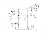
If you look at the circuit (regulator) You will see that it is a copy of the Zen regulator. Only thing missing is the zenerstring from R8 to ground. I also have some big BJT's that I could put in, if that is better.
Steen🙂
What value would you suggest for that resistor, Tschrama?I think a voltage-divider (1 resistor to ground), ensuring at least 5 or 5.5 volt drain-source would enhance the performance of this circuit significantly... 1 resistor could make a lot of differnce here man!
If you look at the circuit (regulator) You will see that it is a copy of the Zen regulator. Only thing missing is the zenerstring from R8 to ground. I also have some big BJT's that I could put in, if that is better.
Steen🙂
Lovely picture, Tony🙂 We could use some of that weather here in Denmark right now. Its all grey and cold here.Here, my Mother, my wife Betty and yours truly…
Steen🙂
and don't worrie about it to much... but it looked like a wasted oppotunity to me that's all .... MOSFET is fine is that position, for BJT you may have to change more values so just leave it the way it is...
... 😉 allthough a BTJ would give you 3 or 4 more Volt output......
... 😉 allthough a BTJ would give you 3 or 4 more Volt output......
Thanks Tschrama🙂
Steen🙂
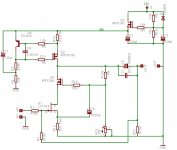
Yes I have thought about that too. Since I have a pair of nice trafo's with 2x25V secondaries I think I will try this one first. See schematic. Looks like a pretty "organic" amp to me.allthough a BTJ would give you 3 or 4 more Volt output......
Steen🙂
Attachments
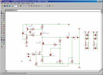
I cleaned up the schematic a bit and added R16 and C7. This will be the first attempt on a Jfet poweramp for me🙂
The picture attached should be a little prettier than the first one.
Steen🙂
The picture attached should be a little prettier than the first one.
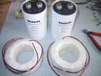
Yes, I was lucky enough to pursuade him into winding some of those for me. I have 4 in my A-X's also 😉Hi Steen, have you bought those inductors directly from Magura?
Steen🙂
Attachments
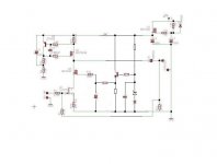
Hi, JH thanks for pointing that out. I think I have a big trafo with 30V secondaries, somewhere in the garage. That might do the trick. There is a minor mistake in the schematic above. The supply voltage above the reg should read 40V.Are you ready to lose 7V or more through Q3 . . . ?
Steen🙂
Nice circuit indeed .. very interested in how it all works out.. the 'cap multiplier' now looks better to me .. you can experiment with leaving R16 out .... indeed the voltage drop is now a additional 3.7 Volt ... so if that's a problem, try it without R16 .. or use different values.. 47k-to-15K ..
goodluck!🙂
goodluck!🙂
Thanks for the kind words, guys🙂
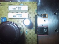
I didnt design boards for this amp, I used perfboards. A nice board would certainly be nice.
BTW I have one channel playing music, but there is something wrong with the other. I will take a look at it tomorrow. In the meantime here is a pic of the little bugger, sitting on its kapton sheet.
Steen😎
I didnt design boards for this amp, I used perfboards. A nice board would certainly be nice.
BTW I have one channel playing music, but there is something wrong with the other. I will take a look at it tomorrow. In the meantime here is a pic of the little bugger, sitting on its kapton sheet.
Steen😎
Attachments
- Status
- Not open for further replies.
- Home
- Amplifiers
- Pass Labs
- ZenV8 with CCS and Capacitance multiplier!