I have a couple of questions regarding the Zener + Emitter Follower voltage regulator on www.tnt-audio.com.
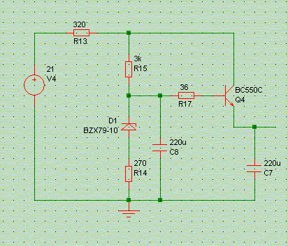
1. What is the max output current of a regulator like this?
2. What type of zener to use for an output of 15V? (15V, xW zener?)
3. Can cap C8 & C7 be polarized?
4. Is the schematic under the right way to make a dual supply?
1. What is the max output current of a regulator like this?
2. What type of zener to use for an output of 15V? (15V, xW zener?)
3. Can cap C8 & C7 be polarized?
4. Is the schematic under the right way to make a dual supply?
Attachments
The max current will be defined by the transistor max current.
Here, with a CD550 I think it's 100mA
the output voltage is Vzener-0.7V, you don't need a high power zener
yes, the caps are polarized (they are electrolytics)
it seems correct
Here, with a CD550 I think it's 100mA
the output voltage is Vzener-0.7V, you don't need a high power zener
yes, the caps are polarized (they are electrolytics)
it seems correct
R13 in the original schematic should not be there, of course, or at least not with such a high value.
It seems I did a lot of copy and paste from a shunt reg schematic for this one ...
It seems I did a lot of copy and paste from a shunt reg schematic for this one ...
Ok so the schematic will work when R13 is removed?
Any suggestions for a good "audiophile" transistor with a higher output current?
Any suggestions for a good "audiophile" transistor with a higher output current?
Don't actually need more than 44-55mA (2x OPA627 and 2x BUF634T in wide BW), but the trafo will be a 2x18V 50VA, so why not? So I can use it for other designs. 🙂
for 50mA the BC550 will be fine, just take care that you don't have more than 10V between the collector and the emitter (otherwise you'll exceed the maximum power dissipation)
If you need more than 70mA, a BD140 will be nice. I think it can dissipate +-1W without heatsink.
But if it's for less than 70mA, i suggest you to stey with the BC550
Generally, transistors that can handle more power have a lower beta. And a higher beta gives a better regulation.
If you need more than 70mA, a BD140 will be nice. I think it can dissipate +-1W without heatsink.
But if it's for less than 70mA, i suggest you to stey with the BC550
Generally, transistors that can handle more power have a lower beta. And a higher beta gives a better regulation.
Yes the BC550C/BC557C combo has a good beta.
BC557C can only dissipate 0.5W though while the BC550C can dissipate 1.5W. What trasistor should I use instead of the BC557C which can dissipate 1.5W with the same (or better?) beta?
BC557C can only dissipate 0.5W though while the BC550C can dissipate 1.5W. What trasistor should I use instead of the BC557C which can dissipate 1.5W with the same (or better?) beta?
the complementary for the BC550 is the BC560
the 557 goes with the 547, and are "standard" transistors. The 550/560 are low noise.
The 550/560 can dissipate 625mW
the 1.5W value is when the junction is at 25°C, 625mW is when the case it at 25°C
the 557 goes with the 547, and are "standard" transistors. The 550/560 are low noise.
The 550/560 can dissipate 625mW
the 1.5W value is when the junction is at 25°C, 625mW is when the case it at 25°C
Werner said:R13 in the original schematic should not be there, of course, or at least not with such a high value.
It seems I did a lot of copy and paste from a shunt reg schematic for this one ...
You should remove both R3 and R13. I guess they are there to trim the output voltage to 15V, but they destroy your zener dynamic impedance, as the 270 Ohms are in series with the zener dynamic imp of a couple of Ohms. If you have a 15V zener and want to trim the output voltage to 15V, use a normal small signal diode like 1N4148 in series with the zener. Gives much better hum and mains borne junk reduction then the 270 ohms.
Another possible improvement is to load the follower with a relatively large standing current of say 50mA with a resistor to ground. Firstly, the added current will decrease the dynamic output impedance, and secondly it will reduce the load current *variations* again improving the performance. For this you need to upgrade to the mentioned BD130/140 though, possibly with a clip-on heatsink.
Jan Didden
janneman said:
You should remove both R3 and R13.
R3, and what it does, are *entirely* intentional.
At least, in the context of my own preamp designs.
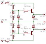
Speaking of which ... I do not recommend the use of the follower 'regulator' for anything other than dual-mono, single-stage, constant-current loads.
So trying to feed a stereo pair of each two opamps from it may work (it does, actually), but also may be far from ideal.
Werner said:R3, and what it does, are *entirely* intentional.
what is R3 there for? I thought it is there to prevent the cap from frying the zener in a discharge / power off. But it does increase the internal resistance of the resister+zener network. I would take out R3 and put in between the cap and the zener (where a wire is).
The cap cannot discharge through the zener, the voltage will be held at the zener voltage. It must take some other route ...
Dave
Dave
Werner said:
R3, and what it does, are *entirely* intentional.[snip].
Werner, I'm sure it is intentional, I do not suppose it is there for fun, but can you tell us *why* it is there?
Jan Didden
Hmmmm.........
Maybe he doesn't care about regulation?
(I gotta stay out of this one...........)
Jocko
Maybe he doesn't care about regulation?
(I gotta stay out of this one...........)
Jocko
janneman said:
You should remove both R3 and R13. I guess they are there to trim the output voltage to 15V, but they destroy your zener dynamic impedance, as the 270 Ohms are in series with the zener dynamic imp of a couple of Ohms. If you have a 15V zener and want to trim the output voltage to 15V, use a normal small signal diode like 1N4148 in series with the zener. Gives much better hum and mains borne junk reduction then the 270 ohms.
Another possible improvement is to load the follower with a relatively large standing current of say 50mA with a resistor to ground. Firstly, the added current will decrease the dynamic output impedance, and secondly it will reduce the load current *variations* again improving the performance. For this you need to upgrade to the mentioned BD130/140 though, possibly with a clip-on heatsink.
Jan Didden
First mod:
For minimized noise should i just simply replace R3/R13 with 1N4148 diodes, or should I keep the resistors?
Second mod:
I think I'll stay with the BC550C/BC560C combo, so the the second mod is out of the question.
Werner said:
R3, and what it does, are *entirely* intentional.
At least, in the context of my own preamp designs.
Speaking of which ... I do not recommend the use of the follower 'regulator' for anything other than dual-mono, single-stage, constant-current loads.
So trying to feed a stereo pair of each two opamps from it may work (it does, actually), but also may be far from ideal.
I'll guess I'll have to build dual-mono then. 🙂
Any recommedations for how much capacitance in front of this voltage regulator I should use when used as dual-mono?
- Status
- Not open for further replies.
- Home
- Amplifiers
- Solid State
- Zener + Emitter Follower voltage regulator