You can choose either type but I would also have a resistor at first. R-C-R-C by that you will have less harmonics. Resistors value of 1-4.7 ohms is OK.Alcaid said:Would you prefer metall oxide or wirewound resistors as R1,R11 and R5,R15?
You can also choose plain metal film as long as you have control over the power and inrush currents. 1-4 metal film is sufficient I think.
peranders said:
You can choose either type but I would also have a resistor at first. R-C-R-C by that you will have less harmonics. Resistors value of 1-4.7 ohms is OK.
You can also choose plain metal film as long as you have control over the power and inrush currents. 1-4 metal film is sufficient I think.
How do I calculate the power dissipated in these resistors?
I'm going to use a toroid (50VA) without any soft start circuitry, so a 1/4W resistor wouldn't survive I guess.
Elso Kwak said:Hello Alcaid, How about this one?
You can use the LM431 or a Sziklai connection in place of the Darlington. A constant current source for the reference improves the sound. If you use an inductor in place of R1 (in your scheme)you will get better ripple rejection.😎
Well, at first I was aiming for simplicity. I've seen your circuit in another thread, and even though I'm getting further and further away from the simple circuit at the beginning, yours seem like too much for me. 🙂
Re: Re: Zener + Emitter Follower voltage regulator
More simple is better???
😕
Alcaid said:
Well, at first I was aiming for simplicity. I've seen your circuit in another thread, and even though I'm getting further and further away from the simple circuit at the beginning, yours seem like too much for me. 🙂
More simple is better???
😕
Re: Re: Re: Zener + Emitter Follower voltage regulator
Not better, cheaper to build 😉
Elso Kwak said:
More simple is better???
😕
Not better, cheaper to build 😉
Alcaid said:
What does the 4k7 do?
Werner said:
Pulls 3mA from the BC550 so that its own output impedance drops to
about 10 Ohms.
BTW, how much current does your load demand?
Is there any benefits of using a smaller resistor there, for instance 3k?
Bricolo said:what's bad with regs using feedback? 😕
I guess nobody want's to answer you question. I would've answered if I only could 😉
It's not bad but you will get different characteristics. Pros and cons with everything.Bricolo said:what's bad with regs using feedback? 😕

Bricolo said:what's bad with regs using feedback? 😕
it diminishes our ability to show others how sophisticated and capable we are by making it so easy to build a quality regulator.
How much current through the zener would you guys recommend?
I have been recommended using a constant current diode of 0.5mA, but is't that a little low?
I have been recommended using a constant current diode of 0.5mA, but is't that a little low?
Check the V-I curve of the zener and bias for a point
of sufficient stability. In addition, zener voltage noise is inverse
proportiional to the square root of current.
of sufficient stability. In addition, zener voltage noise is inverse
proportiional to the square root of current.
The tests in the datasheet where done with 5ma current. Is this a good value to go for? (Good... I want the BEST 😉)
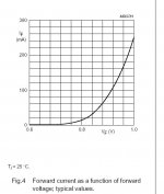
Alcaid said:Do you mean this graph?
Don't understand how to find the right value.
It's a BZX 79 15V zener.
This is the graph for the forward current. You need the one for the reverse current. Then find a spot where it is relatively flat.
Jan Didden
Well, the V-I diagram with the reverse current isn't in the datasheet. Where can I find it then? anyone?
You won't find it... but the parameter "dynamic resistance" can be useful. This parameter says how much the curve is going up, the slope, upwards.Alcaid said:Well, the V-I diagram with the reverse current isn't in the datasheet. Where can I find it then? anyone?
That is correct. Look in the table differential resistance for your zener, I think it was a 9.1V zener?
You will see that at 5mA reverse current the dynamic impedance is max 15 ohms. That 5mA also seems the current where the zener voltage variation is closely centered around 9.1V, so that seems a good value.
I didn't realise they stopped publishing the reverse characteristics. Probably too many cook-book technicians not understanding those curves anyway. Oh well, such is the price of progress...
Jan Didden
- Status
- Not open for further replies.
- Home
- Amplifiers
- Solid State
- Zener + Emitter Follower voltage regulator