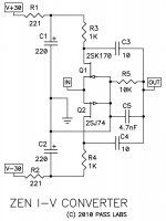
This is a quick & dirty schematics just to show the idea of a cascoded complementary JFET IV.
I hesistated to call it cascoded Zen IV, as it is more of a "Blowtorch IV".
Balanced DAC current is fed to the sources of the input jfets, whose gates are tied to ground.
R2,3,19,21 are bias resistors for the folded cascode MOSFETs (say 200R).
Conversion gain (I to V) is set by R22,24.
One may add additional electrolytic caps to parallel R5,6,16,17.
And R1/18, R4/20 can be replaced by constant current diodes for further improved PSRR.
The rails can now be quick a bit lower than +/-30V.
And the choice is not affected by changes in IV conversion gain and first stage bias.
So one can increase R22,24 (say to 2.4k) and use multiple JFETs in parallel without changing Vsupply.
When using JFETs in parallel, R2,3,19,21 wants to be reduced by N (no.of JFETs in parallel).
No coupling output caps, but consumes quick a bit more current.
Patrick
Problem with this is you would be stuck with balanced ouput and the input would require 2 extra DACs. R2R DAC chips aren't chip or easy to find these days.
If you forgo the coupling caps, the output would be around 0V, I would think that a simple servo filtered below 1 hz or less could null the DC offset and be cheaper than buying a quad blackgates. The lower cost would keep it Zen-like IMO 😉
If you forgo the coupling caps, the output would be around 0 V DC since this is split supplied. Can't see a reason not to DC servo unless you just happen to have 4 expensive blackgates in your pocket 🙂
Just came across this new I/V stage which looks damn good 😀
I made a .pdf file of the article which I found a little hard to find inside DiyAudio, that could probably be attached on the first post too 😎
Best regards,
nAr
I made a .pdf file of the article which I found a little hard to find inside DiyAudio, that could probably be attached on the first post too 😎
Best regards,
nAr
Attachments
Last edited:
there are some funny parts , placed in drains of each jfet ;
they're called resistors , and they're handy for decreasing voltage in appropriate nodes

Hihihi😎
I could have used my brain...
Hihihi😎
I could have used my brain...
Its fine, I'm using mine trying to figure out a DC servo scheme to eliminate the expensive sound degrading coupling caps. Wish I knew SPICE.
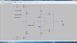
Anyone have a Spice model for this up and running yet ?
Hi guys,
Two of my favorite topics: UGS and IV converters.....in no particular order!
Philippe: since you use the ad1865 current mode is it safe to assume that this chip expects 0V at that pin ?
I'm thinking of trying this with a 1738 ( in a Shanling CD Player ) which expects 2.5V at the current output pin.
Just to compare with a Drek conversion i did with Zen-Mod's precious 😎 help 🙂
I made a mother board for IVs and PSU just so i could test different solutions....here is the chance.
Not that i'm unhappy with what i got but DIY is an itch that doesn't go away.........
Late edit: I'm curious about the UGS solution by will invest my effort on the present ZEN IV.
Last edited:
Maybe some of us, actually a lot of us don't like the sound of heavy NFB. I would say Mr PA0SU that this isn't the place to Pimp your website. You are kind of insulting a highly regarded designer and many of us take offense.
And Thankyou Mr Pass for sharing this new design with us, we do appreciate it.
And Thankyou Mr Pass for sharing this new design with us, we do appreciate it.
Hi guys,
Two of my favorite topics: UGS and IV converters.....in no particular order!
Philippe has posted a UGS based IV in the article coments,since one has to use use the ad1865 ( in his particular case ) current mode is it safe to assume that this chip expects 0V at that pin ?
I'm thinking of trying this ( ZEVN IV ) with a 1738 ( in a Shanling CD Player ) which expects 2.5V at the current output pin.
Just to compare with a Drek conversion i did with Zen-Mod's precious 🙂😎help
I made a mother board for IVs and PSU just so i could test different solutions....here is the chance.
.. to eliminate the expensive sound degrading coupling caps....
How about using 0.1uF instead of bulky 10uF? It's possible if the ZEN I/V is loaded by B1 running at approx. +/-10V (it's easy to scale down from +/-30V). Additional benefit is higher drive capability.
Very nice, loved the D1 for long time . Will try this as soon I will find a nice usb or spdif dac with current output .
Any suggestions ??
Any suggestions ??
You are kind of insulting a highly regarded designer .....
Pfuuuh... it seems to be real hot stuff!
BTW you have no idea about my design experiance, but if I am on the wrong tour......... I'm so sorry.
Herb.
Pfuuuh... it seems to be real hot stuff!
BTW you have no idea about my design experiance, but if I am on the wrong tour......... I'm so sorry.
Herb.
The Zen I/V Converter article is posted here at DIYAudio,
and I am establishing this thread for discussion.
At this moment, it seems to have lost the first diagram, that
of a typical inverting op amp with a virtual ground input,
but I'm sure that will be rectified shortly.
😎
I have just seen the circuit. 😀
My first thought. Wy did i not come up with that idear! 🙂😡🙂😡
Nelson i am a bit envious! I have to say....
The only thing that bothers me is that the 2sj74 and and 2sk170 is difficult to get you hands on through newark, farnell, mouser and digikey.
But excellent and simple design.
PS: The input will be a virtual ground. Even if the feedback is high impedance.
Last edited:
Thanks for the info.
I maybe have a little "but".
R5 and C5. Should the not have been feed back to source instead of ground.
I think there is a little drawing failure,
Attachments
Thanks for the info.
I maybe have a little "but".
R5 and C5. Should the not have been feed back to source instead of ground.
I think there is a little drawing failure,
Sorry i was'nt finished.
I know that you state no feedback and that mades it even more impressive regarding the performance curves. Feedback would rase the performance even more?!?!?! Nelson ?? Am i right or wrong?
Hello Mr.Pass,
It is possible to have more detailed measurements for Zen I/V - harmonics levels up to 7th, the contamination spectrum, if possible?
You don't intend to use it for HD signals (such as 24/96 or 24/192) with provided FR, is it correct?
The FR can be adjusted by replacing the filter cap, if necessary, do you have any other samples of FR for different input signals, by any chance?
Thanks!
thanh1973
I am still interested in op amps (less for I/V stage of course), these for example are also op amps HD Audio Opamp
Last edited:
Anyone have a Spice model for this up and running yet ?
FFT of 4V peak into 50k load
Attachments
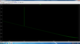
FFT of 4V peak into 50k load
You missed 10K/4n7 on output , they are the load too!
They are optional parts.
If you want me to post it I will but the results are virtually the same (ie 3/5 of FA)
If you want me to post it I will but the results are virtually the same (ie 3/5 of FA)
- Home
- Amplifiers
- Pass Labs
- Zen I/V Converter